Meaning
An electronic circuit topology performs the function of calculating the arithmetic mean of an input signal voltage over a predefined time window to provide a stable measurement output. The linear average detector processes rectified waveforms by smoothing rapid fluctuations through a low pass filter mechanism. Operation stops at the threshold where the sampling frequency fails to capture the intended signal bandwidth or when the input impedance becomes too low to maintain signal integrity.
Signal stability relies on the integration of the voltage levels before the stage provides a DC equivalent for further system processing.
Signal Precision
High performance radio frequency systems demand accurate extraction of signal envelopes for power monitoring or modulation depth analysis. A linear average detector provides the steady value needed for these tasks by ignoring transient spikes that would otherwise skew a true RMS reading. Engineers select this topology when the application requires a simple conversion of amplitude rather than complex power mapping.
Proper gain stages prevent the compression of the input signal before the averaging circuit processes the waveform. The output accuracy remains tied to the quality of the capacitor used within the filter section to prevent leakage currents. Calibration against a known reference source confirms the conversion factor between the peak input and the averaged output.
Thermal drift in the diodes often requires temperature compensation circuits to keep the measurement consistent across the operating range of the hardware.
Circuit Integration
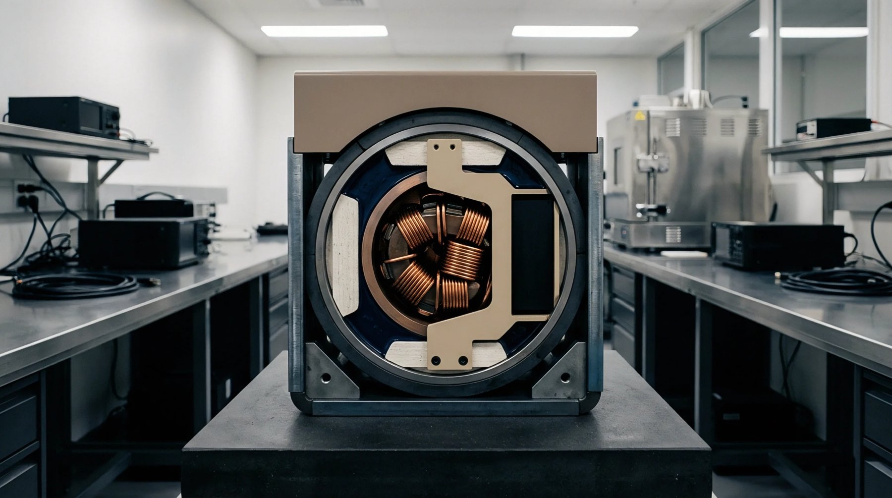
Hardware designers house these components inside shielding enclosures to prevent electromagnetic interference from distorting the low amplitude signals before processing. A linear average detector mounts adjacent to the output stage of a receiver to provide real time feedback on signal strength. Integration involves balancing the time constant of the filter against the expected rate of change in the input signal to avoid lag or excessive jitter.
Too short a window allows noise to penetrate the reading while too long a window blinds the system to sudden changes in signal power. Proper layout practices isolate the sensitive analog traces from digital switching noise to ensure the DC value remains quiet. Voltage stability at the supply pins influences the linearity of the conversion, so designers place bypass capacitors close to the active elements.
Boundary Condition
Operation of these devices ceases when the frequency of the input signal drops near the cutoff frequency of the averaging filter itself. A linear average detector fails to produce a useful result if the signal contains high levels of harmonic distortion that the filter cannot reject. Performance degrades whenever the input impedance mismatch causes significant reflections that alter the voltage levels before rectification.
Sensitivity decreases as the signal level approaches the forward voltage drop of the internal diodes used for rectification. Constraints on the dynamic range limit the utility of the circuit in scenarios where the signal amplitude varies across several orders of magnitude. The detector provides a reliable output for narrow band signals where the envelope remains predictable and stable.