Meaning
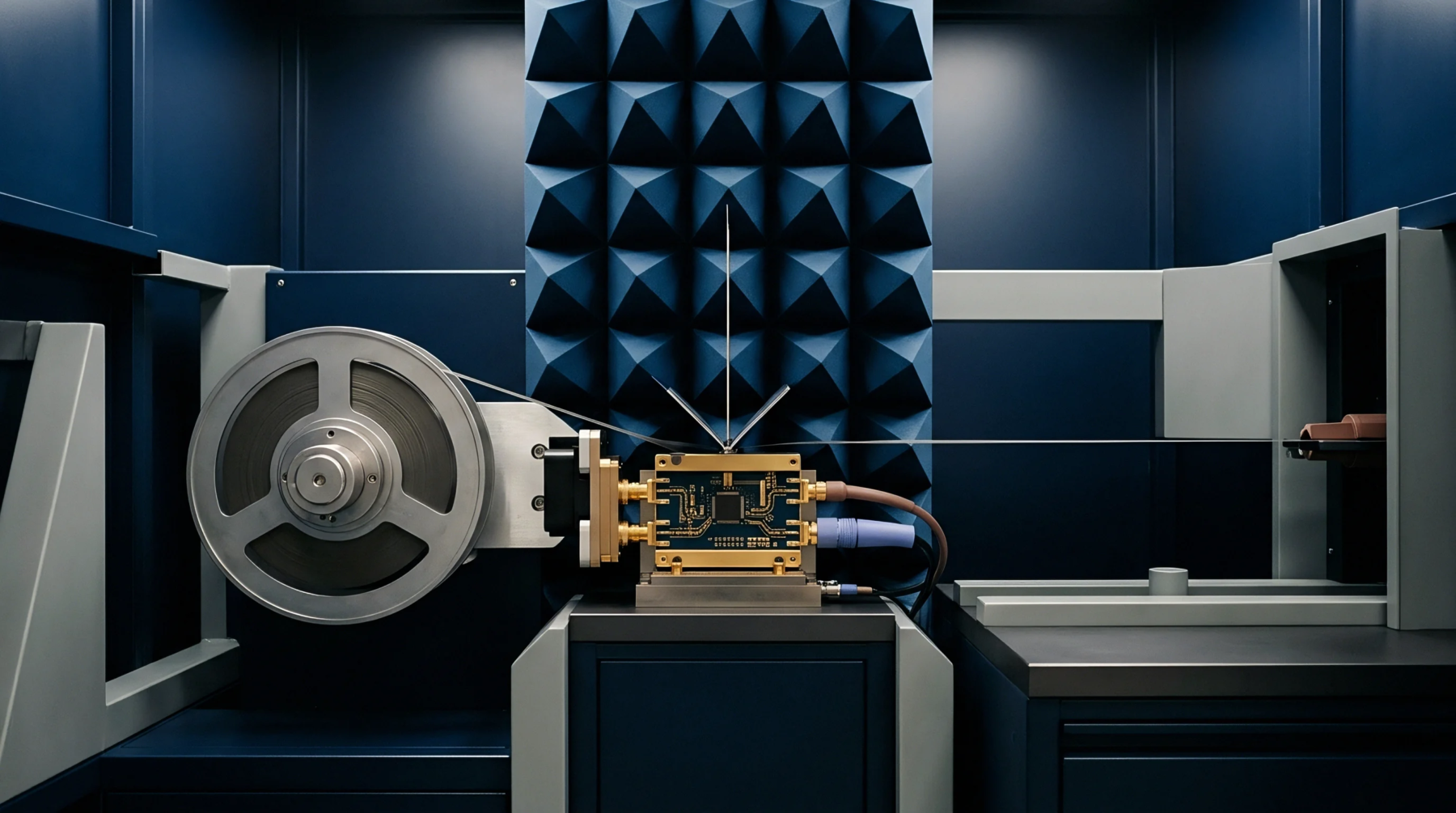
Planar scanning methodology captures the magnitude and phase of the field radiated by an antenna across a two dimensional grid in the immediate vicinity of the aperture. Utilizing planar near field scanning allows engineers to characterize high gain antennas in a smaller space than is required for traditional far field ranges.
Mathematical Transformation
Numerical algorithms convert the complex field data collected on the scan plane into far field radiation patterns. Through the application of a fast Fourier transform, the planar near field scanning data reveals the directional gain and side lobe levels of the antenna. This process assumes that the radiated energy is primarily directed toward the scan plane, making it unsuitable for omnidirectional antennas.
The accuracy of the far field prediction depends on the size of the scan area relative to the antenna size.
Measurement Hardware
Accuracy in the final result depends heavily on the alignment and positioning of the probe as it moves across the grid. The planar near field scanning system uses high precision linear stages to maintain a constant distance between the probe and the antenna under test. Any deviation in the flatness of the scan plane introduces phase errors that distort the calculated far field pattern.
Laser tracking systems often monitor the probe position in real time to correct for mechanical vibrations or thermal expansion of the scanner frame.
Diagnostic Capability
Visualization of the field distribution directly at the antenna surface helps designers identify specific elements that are not performing correctly. Unlike far field measurements, planar near field scanning provides localized information that can pinpoint a failed phase shifter or a poorly soldered connection within an array. This diagnostic power makes it a valuable tool during the prototype debugging phase.
Engineers use these maps to verify that the energy distribution matches the intended taper and phase profile.