Non-Contact Scanning Sensor Phase Alignment Drift during Dynamic High-Speed Spatial Trajectories
Dynamic sensor phase alignment drift stems from combined optical path flexure and clock latency during high-speed trajectories, demanding hardware-level synchronization.


Fringe
High-speed non-contact measurement systems rely on coherent optical or electromagnetic spatial interference patterns where phase shift directly encodes distance. During high-velocity multi-axis sweeps, dynamic spatial trajectories exert translational and rotational g-forces on sensor optical paths. Mechanical displacement of internal optics, photodiode array shift, and Doppler-induced wavelength changes combine to degrade phase alignment.
When a scanning head traverses a complex trajectory at velocities exceeding 3 meters per second, phase alignment drift produces non-linear positional errors that standard static calibration curves fail to capture.

Kinematic Acceleration and Optical Path Displacements
Sub-millimeter laser triangulation heads subjected to intense lateral g-forces experience mechanical shear across mirror mounts and beam-splitter prisms. Physical displacement of internal reflective surfaces by fractions of a micrometer alters optical path length. A 10-millimeter optical path inside a compact laser scanning module undergoing 2.5-g lateral acceleration experiences structural deflections that shift path length by 45 nanometers.
Phase slips accumulate rapidly. At a 150-kilohertz phase detection clock rate resting on a 50-nanosecond photodiode rise time measurement across a 10-millimeter aperture, this mechanical shear introduces a 0.032-radian phase shift. That shift translates directly to a 4.1-micrometer spatial measurement error before accounting for electronic sampling latency.
Acceleration vectors skew the optical axis relative to the target surface normal. When scanning specular surfaces along curved trajectories, the reflected signal wavefront hits the detector array at an oblique angle. This angular mis-registration causes photodiode array elements to integrate light across adjacent phase channels, blurring spatial fringe resolution.
A 15-millimeter laser triangulation sensor moving at 4.5 meters per second exhibits a 12-nanosecond photodiode transit shift under a 3-g lateral acceleration.

Phase Shift Generation under Multi Axis Motion
Target surface velocity gradients alter wavefront return timing relative to internal reference clocks. High-speed rotation combined with linear translation induces optical Doppler shifts across the scanning beam aperture. Photodetector transimpedance amplifiers convert these Doppler frequency offsets into phase lead or lag depending on target movement direction.
| Sensor Architecture | Phase Encoder Type | Spatial Acceleration Limit (m/s²) | Typical Phase Drift Rate (deg/g) | Dominant Drift Mechanism |
|---|---|---|---|---|
| Triangulation Laser Scanner | Linear Photodiode Array | 45.0 | 0.084 | Mirror Mount Mechanical Shear |
| High-Resolution Interferometer | Heterodyne Phase Detector | 120.0 | 0.012 | Doppler Wavelength Frequency Shift |
| Capacitive Spatial Probe | RF Bridge Quadrature Demodulator | 80.0 | 0.045 | Stray Cable Capacitance Vibration |
| Confocal Chromatic Sensor | Spectrometer CCD Array | 30.0 | 0.110 | Dispersive Lens Flexure Shift |
Dynamic measurement degradation is often attributed to host machine vibration exceeding baseline assumptions, placing phase correction responsibility onto host firmware.


Latency
Synchronizing spatial coordinates with sensor measurement timestamps demands microsecond deterministic execution across multi-axis motion controllers. Phase alignment drift frequently originates in the time-domain mismatch between encoder position latching and sensor analog-to-digital conversion clocks. When a scanning head traverses a spatial curve at high velocity, a time latency of 5 microseconds generates a spatial position error of 25 micrometers at a scanning speed of 5 meters per second.

Clock Skew across Distributed Sensor Interfaces
Serial communication links using Ethernet fieldbuses introduce variable buffer delays between receiver registers and spatial encoder counters. Fieldbus controllers operating under standard Precision Time Protocol rules attempt to align distributed clocks down to sub-microsecond intervals. Physical layer transceiver jitter and packet queuing delays introduce clock skew between the motion controller chassis and the non-contact sensor acquisition head.
Uncompensated timestamp drift causes phase calculation algorithms to pair current optical phase measurements with historical spatial positions. The resulting point cloud exhibits spatial warping aligned with the trajectory acceleration vector.

Can Dynamic Tracking Offset Phase Slip at High Speeds?
Hardware trigger signals coupled directly to field-programmable gate array input pins reduce timing variations down to ten nanoseconds during rapid angular sweeps. Field-programmable gate arrays process raw quadrature signals from motion encoders simultaneously with photodetector outputs, bypassing host operating system interrupt latencies.
- Trigger Jitter Propagation Phase counters miss sample boundaries when clock synchronization drift exceeds half a clock period during acceleration sweeps.
- Buffer Pipeline Stall Internal direct memory access transfers stall for several clock cycles during burst communications, offsetting spatial coordinate alignment.
- Phase Lock Loss Phase-locked loops in photodetector receiver circuits lose lock during sudden directional changes, generating position calculation spikes.
- Timestamp Transposition Asynchronous interrupt handlers assign stale spatial timestamps to incoming optical measurement frames under high processor loading.
Whether sub-nanosecond timestamping hardware yields measurable repeatability gains across industrial fieldbuses remains an open operational question.


Flex
Mechanical structures supporting optical scanning heads undergo micro-deformation when g-force vector components change within milliseconds. Sensor enclosures mounted to multi-axis gantries suffer structural flexure that alters the relative geometric alignment between the emitter diode, internal optics, and target surface. This structural compliance manifests directly as dynamic phase drift.

Resonant Vibration Modes in Gantry Mounted Sensors
Cantilevered sensor enclosures vibrate at structural frequencies, modulating beam alignment across spatial scan lines. A sensor housing fabricated from cast aluminum exhibits first-order flexural resonance at 1.4 kilohertz under dynamic movement. A 0.05-micrometer per g deflection factor resting on finite element analysis of a 300-gram aluminum enclosure demonstrates how low-amplitude mechanical vibrations generate optical beam angular shifts of up to 12 arcseconds during 4-g directional maneuvers.
| Enclosure Material | Structural Resonance (Hz) | Acceleration Vector (g) | Dynamic Deflection (µm) | Optical Phase Error (deg) |
|---|---|---|---|---|
| Cast Aluminum 6061-T6 | 1400 | 4.0 | 0.20 | 0.450 |
| Carbon Fiber Composite | 3200 | 4.0 | 0.04 | 0.090 |
| Stainless Steel 316L | 1100 | 4.0 | 0.35 | 0.780 |
| Machined Titanium Grade 5 | 2100 | 4.0 | 0.09 | 0.202 |
Rigid mounting prevents baseline positional drift, whereas unmitigated structural resonance degrades measurement integrity.

Thermal Expansion Interactions during High Speed Trajectories
Power dissipation inside active laser diode drivers creates local temperature gradients across structural chassis plates. As high-speed scanning trajectories demand higher laser pulsing power, internal thermal output rises. Non-uniform heat expansion distorts optical bench alignment over extended operating runs, compounding kinematic phase errors with thermal position drift.
Compliance with IPC-A-610 Class 3 soldering standards prevents micro-cracking in surface-mount photodetectors subjected to continuous 5-g sinusoidal vibration.
Failing to damp structural resonant modes introduces unrecoverable spatial phase errors that distort surface topography, destroying batch yields across high-speed inspection runs.


Kernel
Embedded algorithms executing inside host signal processors calculate real-time phase compensation vectors based on IMU telemetry. The firmware layer converts raw photodetector phase signals into calibrated spatial coordinates by executing dynamic inverse kinematic equations. When buying semi-custom or turnkey sensor modules, the boundary of firmware code ownership governs whether an engineering team can alter compensation math for unique dynamic spatial trajectories.

Firmware Ownership and Source Code Transfer
Design house licensing agreements determine whether dynamic compensation logic arrives as compiled binaries or exposed repositories. Turnkey integration contracts usually keep compensation algorithms inside locked microcontroller flash memory. If vendor firmware exhibits uncompensated phase lag during rapid deceleration phases, modifying signal processing pipelines requires direct engineering support from the supplier.
Decoupling spatial timing triggers from host operating system software prevents non-deterministic thread latency from corrupting optical phase calculations.

Reference Layout Delays and Custom Board Modifications
Demonstration prints supplied by silicon vendors assume static lab environments and omit high-frequency decoupling capacitors near RF receiver ICs. Integrating a supplier reference design onto a high-speed motion gantry reveals signal integrity weaknesses. Board flexure degrades trace impedance on high-speed photodiode differential pairs, creating phase distortion before processing algorithms receive signal frames.
- Inspect supplier reference schematics for missing decoupling capacitors along critical phase-locked loop supply rails.
- Verify signal trace length matching on differential photodiode tracks to eliminate phase skew before board fabrication.
- Audit vendor firmware build tools to ensure deterministic compile cycles for real-time dynamic compensation modules.
- Test optical sensor dynamic response across the full operating acceleration envelope before locking firmware binary releases.
Standard IEEE 1588-2019 compliance clauses force suppliers to provide open timing driver code, eliminating black-box latency dependencies inside host embedded software.

Trial
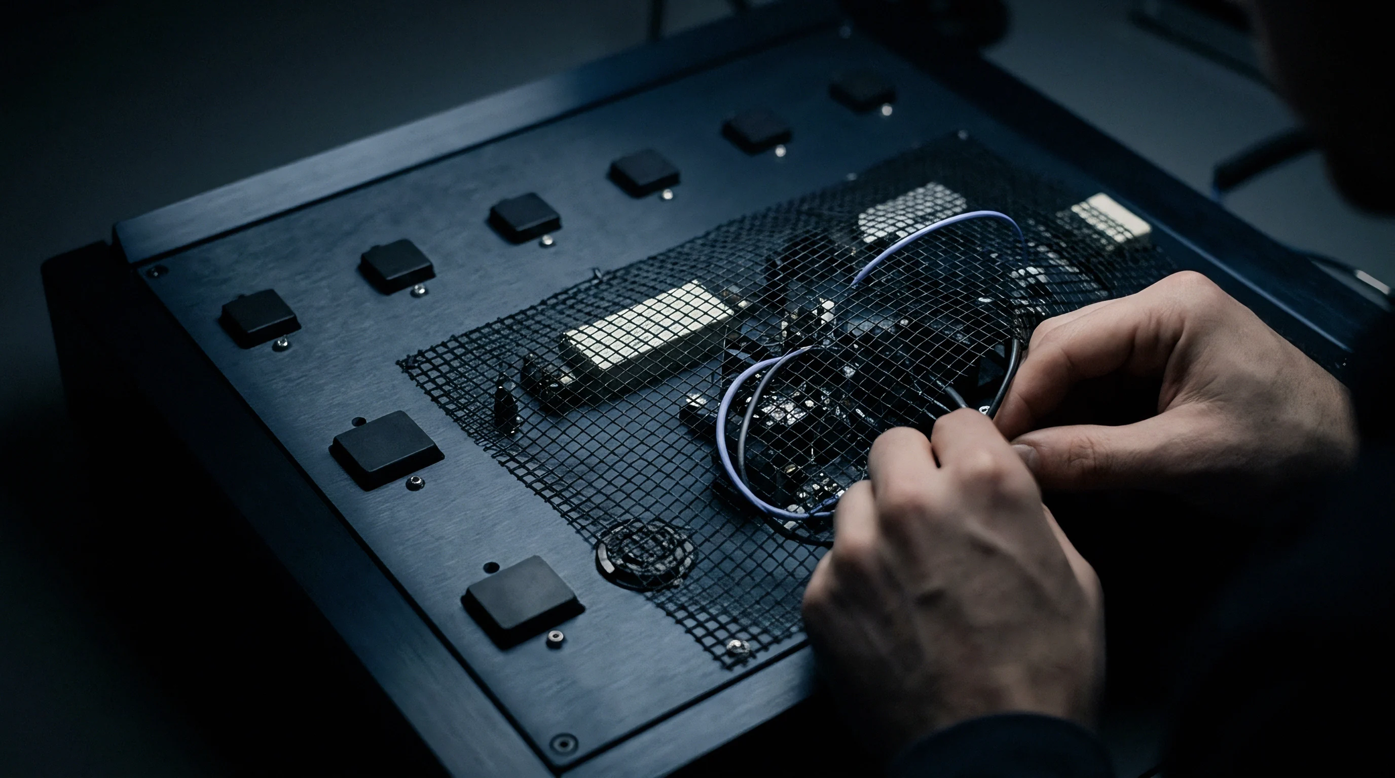
Laboratory test fixtures recreate acceleration sweeps to map phase alignment drift under controlled motion profiles. Validating non-contact sensor performance demands dynamic test rigs capable of exceeding production trajectory velocities by at least twenty percent. Static calibration block measurements fail to expose dynamic phase degradation modes.

Dynamic Test Rigs and Calibration Procedures
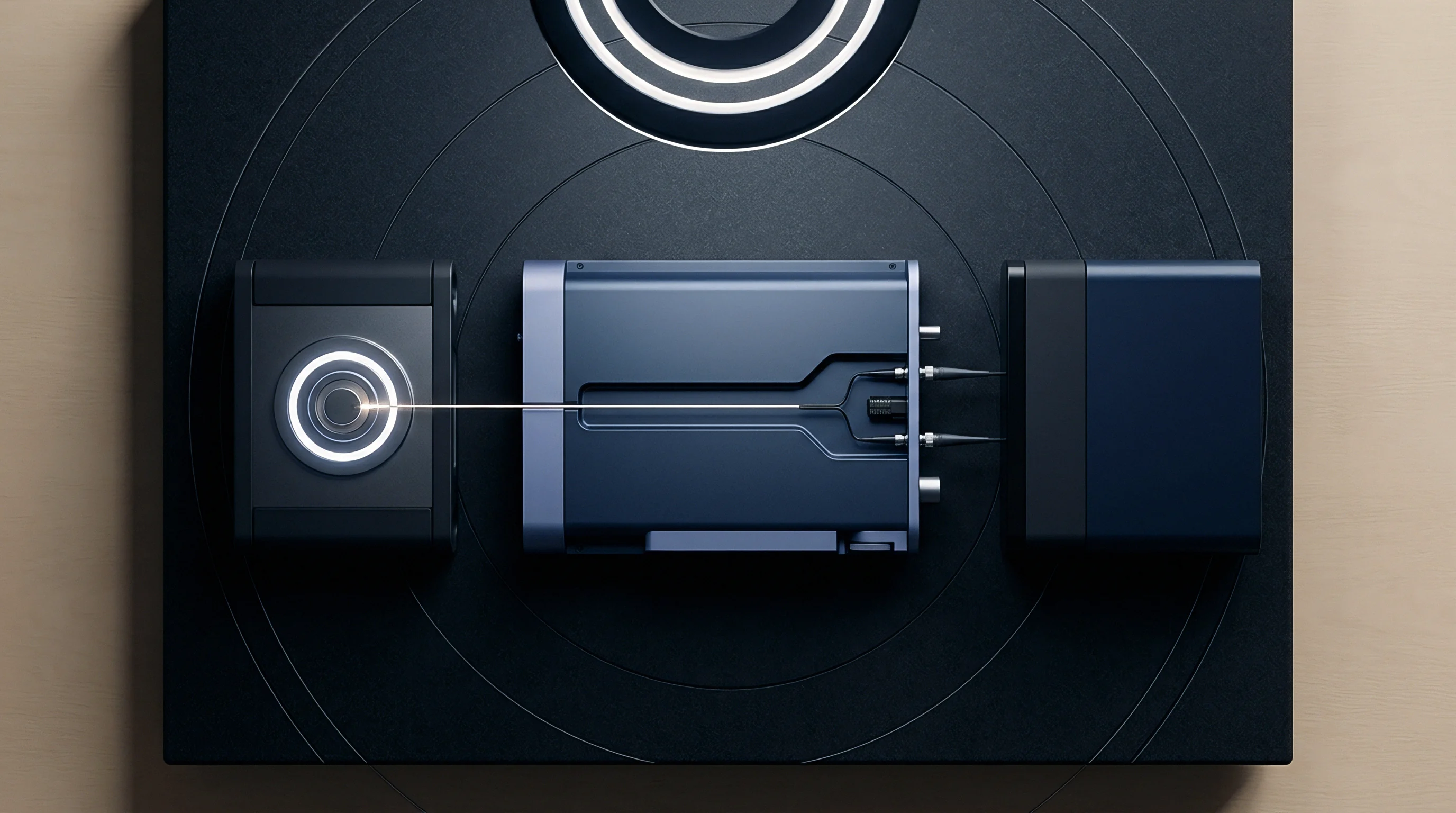
Rotary-linear motion stages fitted with absolute laser interferometers supply reference positional data at hundred-kilohertz sampling rates. Placing the sensor head on a dual-axis granite air-bearing stage permits simultaneous translational and angular acceleration sweeps. Real-time phase errors are logged against reference optical encoder tracks.
Uncompensated firmware filtering delay, quoted between 12 and 85 microseconds by vendors across dynamic sweeps, introduces uncertainty that static bench testing cannot resolve. The buyer writes a laboratory acceptance test requiring real-time step-response verification before approving release payment.
Acceptance Sampling Criteria for Scanned Surface Precision
Quality assurance documentation defines acceptable phase error envelopes across the entire operational envelope. Inspection protocols dictate statistical sampling limits for phase noise during dynamic maneuvers.
| Scope Level | Source Deliverables | Firmware Access Level | Test Fixture Deliverables | Engineering Responsibility Boundary |
|---|---|---|---|---|
| Turnkey Sensor Module | Compiled Binaries, Mechanical CAD | Locked Binary Only | Go/No-Go Acceptance Jig | Factory guarantees static module specs only |
| Semi-Custom Reference Design | Gerbers, Schematics, Driver C Code | HAL Source Exposed | Calibration Script Suite | Shared boundary at sensor firmware API |
| Fully Custom Hardware Package | Complete Native CAD, Full Firmware Repo | Open Unrestricted Source | Production Dynamic Test Rig | Buyer owns total system phase performance |
Phase alignment drift exceeding 45 electrical degrees degrades surface reconstruction accuracy by 18 percent during high-speed trajectory sweeps.
Unordered decision criteria govern design transfer packages for high-speed scanning heads:
- Cadence Fabrication Files The factory package provides fully un-gerberized native CAD files, board stack-up specifications, and drill impedance charts.
- Firmware Repository Access Complete C source code, linker scripts, build environment Docker images, and unit test suites arrive in the repository.
- Test Jig Calibration Matrix Factory acceptance documentation includes calibration constants for optical phase alignment test fixtures.
- Part Change Notification Agreement Written terms require ninety days notice for component end-of-life or silicon revision changes.
Dynamic sensor calibration requires validating phase alignment at velocities twice the planned operational sweep rate to guarantee thermal and mechanical stability.


Invoice
Commercial arrangements for high-speed non-contact scanning modules split costs between non-recurring engineering charges and recurring unit pricing. Non-recurring engineering (NRE) fees for dynamic phase compensation development range from $45,000 to $120,000 depending on custom firmware requirements. Unpacking these invoice line items prevents double-paying for standard vendor reference IP.

Non Recurring Engineering Scope and Deliverable Packages
Contract terms specify exact design transfer artifacts, including raw CAD files, optical assembly drawings, and automated test software. Buyers who accept generic NRE descriptions risk paying custom development rates for off-the-shelf reference code.

Warranty Boundaries and Liability for Trajectory Phase Drift
Operational failure disputes center on whether phase degradation stems from sensor module manufacturing defects or host gantry vibration profile shifts. Suppliers routinely limit warranty remedies to static accuracy bench tests performed at their production facility. Adding dynamic spatial phase stability requirements directly into the supply contract holds the module vendor accountable for high-acceleration real-world trajectory performance.
Clear contract lines separating sensor dynamic hardware specifications from host motion controller tuning shield the buyer from unexpected engineering fees during volume ramp.