Kinematic Alignment Drift in Automated Multi-Axis Electronic Test Stations
Kinematic drift in multi-axis test stations stems from thermal gradients and contact fretting, demanding hardened seats and active vision recalibration.


Mount
Capacitive displacement sensors detect a 4.2 micrometer offset along the vertical axis of a multi-axis microwave test head at three in the morning. Even though the test cell housing the station maintains ambient room temperature within two degrees Celsius, the contact points locating the floating probe fixture shift enough to break RF pad contact ~ well beyond the 2.5 micrometer pitch placement repeatability required for high-frequency coplanar waveguide probes rated to 67 gigahertz on gold bond pads.
Precision multi-axis test stations isolate device carriers using kinematic mounts that define six spatial degrees of freedom through six distinct contact points. Fastening a precision nest with four dowel pins and six perimeter cap screws creates mechanical overconstraint, warping the plate as clamping loads shift during production. Pairing three spherical surfaces with matching base plate geometry provides true kinematic constraint, keeping internal stress from building up.
A Grade 5 silicon nitride ball seated in a tungsten carbide vee groove maintains lateral positioning within 0.3 micrometers across 250,000 clamp cycles under a 15 Newton seating preload.
Automated stations locate the moving test nest against the stage carriage with either Maxwell or Kelvin couplings. A Maxwell coupling uses three V-grooves cut into the base at 120-degree intervals, all oriented toward the platform center, mating with three spherical contact pads on the tooling plate to keep thermal expansion symmetrical along radial vectors. A Kelvin coupling replaces those identical grooves with a trihedral cone, a single V-groove, and a flat landing pad, fixing a deterministic spatial datum point at the center of the cone.

Kinematic Constraints and Degree of Freedom Decoupling
Exact constraint design pairs six independent physical contact points against six spatial degrees of freedom to locate fixtures repeatably. When automated pneumatic lifters bring a device carrier against the test nest, each contact point transmits load normal to its mating face without generating parasitic bending moments. As long as contact vectors remain perpendicular to their contact planes, the mathematical coupling matrix maintains full rank.
Non-kinematic assemblies undergo elastic deformation within aluminum fixture plates whenever mounting hardware tightens unevenly. As that strain relaxes over thousands of test cycles, it introduces positional drift that software calibration cannot predict. Kinematic mounts accommodate structural micro-movement because contact balls seat deterministically in their grooves without binding.

Contact Point Hertzian Stress and Material Selection
Ball diameters between 6 mm and 10 mm concentrate clamping preloads onto contact patches only 40 to 80 micrometers across. Under typical 20-Newton pneumatic preloads, Hertzian contact pressures frequently exceed 1,200 megapascals, easily crushing soft tool steels and anodized coatings into plastic deformation.
Machining kinematic vee grooves directly into 6061-T6 aluminum bed plates leads directly to operational failure. Within several hundred test cycles, repeated impacts from steel balls create localized indentations ~ brinelling ~ in bare aluminum. Reliable test stations press hardened inserts into the chassis instead, resisting local yield and preventing fretting corrosion.
| Spherical Ball Material | Groove Insert Material | Hertzian Stress at 20 N Preload (MPa) | Indentation Depth after 100,000 Cycles (um) | Thermal Conductivity (W/m-K) | Thermal Expansion Coefficient (ppm/K) |
|---|---|---|---|---|---|
| Grade 5 Silicon Nitride (Si3N4) | Tungsten Carbide (WC-6Co) | 1,420 | 0.08 | 30.0 | 3.2 |
| 440C Hardened Stainless Steel | 440C Stainless Steel (58 HRC) | 1,080 | 0.74 | 24.2 | 10.2 |
| Grade 25 Silicon Nitride (Si3N4) | Tool Steel A2 (60 HRC) | 1,210 | 0.45 | 30.0 | 3.2 |
| 440C Hardened Stainless Steel | Electroless Nickel Plated Steel | 980 | 1.85 | 45.0 | 12.0 |
| Tungsten Carbide (WC-6Co) | Tungsten Carbide (WC-6Co) | 1,680 | 0.04 | 100.0 | 4.8 |
Pairing ceramic silicon nitride balls with tungsten carbide inserts prevents metal galling and limits mechanical wear to sub-tenth-micron levels over years of testing. The difference in material hardness stops cold welding while suppressing fretting under rapid pneumatic cycling.
Any mechanical compliance deliberately or accidentally left in kinematic contact points compromises positional stability during high-speed automated runs.

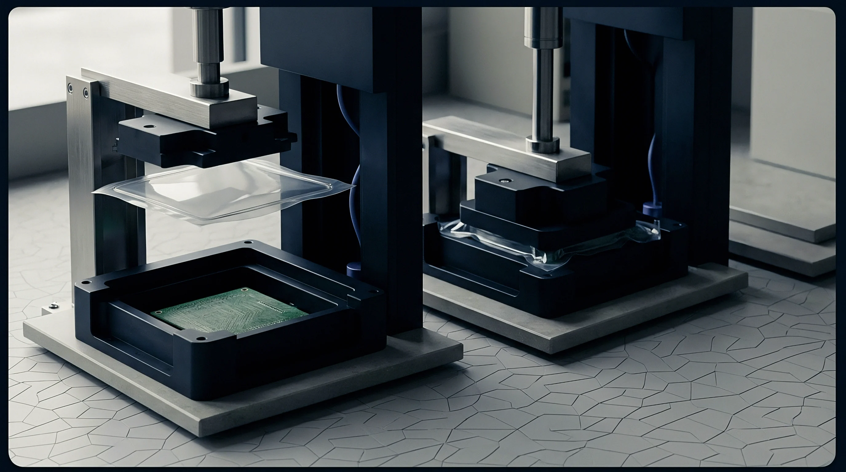
Slip
When thermal gradients build up across a station bed plate, tangential friction along the spherical seating line can overcome mechanical restoring forces. Multi-axis automated test stations run continuous production cycles where voice coil linear actuators, pneumatic ejectors, and high-speed servos dump heat into cast machine beds, creating temperature differentials that force micro-scale sliding between kinematic balls and their receiving grooves.
In theory, kinematic mounts accommodate thermal growth through frictionless radial movement along each groove. In practice, real contact surfaces carry friction coefficients between 0.10 and 0.25 based on surface finish and lubrication. As the base expands, friction pins the contact ball until internal thermal stress exceeds static friction, releasing stored energy in sudden stick-slip jumps.
Frictional heat generated by high-speed linear voice coil actuators drives localized thermal gradients that displace the kinematic seating planes before air handling systems can respond.
Station position sensors miss these stick-slip jumps because optical encoders sit on the linear axis rails rather than at the probe tip itself. Consequently, the motion carriage reports nominal absolute coordinates while the kinematically mounted test socket remains tilted three to seven micrometers out of position where thermal expansion shifted the reference plane.

Which Mechanical Interfaces Yield First?
High-cycle test heads fail most often at the interface between the pneumatic clamping cylinder and the floating tooling plate. Side-loading from the actuator introduces unconstrained bending moments into the kinematic nest, forcing spherical contacts up the inclined walls of the V-grooves. Continuous multi-axis operation degrades these mechanical interfaces first:
- Pneumatic Cylinder Rod Coupling introduces asymmetric lateral loading into the floating nest during rapid stroke engagements, pulling kinematic balls out of their seats unevenly.
- Hertzian Point Fretting Zones generate microscopic oxidized debris inside dry V-grooves, altering friction and triggering unpredictable stick-slip displacement.
- Cable Loom Umbilical Clamps exert continuous torsional torque on the multi-axis stage as carriages travel between component pick positions and fixed RF probe heads.
When pneumatic cylinders pull test fixtures down onto kinematic seats, minor misalignment in the cylinder shaft exerts lateral thrust that introduces unmodeled angular tilt. That side force drives contact balls up the groove walls, leaving the fixture parked in a metastably displaced, high-energy position.

Thermal Expansion Gradients and Actuator Dissipation
Linear voice coil actuators and rotary servomotors dump between 40 and 150 watts of heat into cast aluminum tooling plates. A three-degree Celsius temperature variation across a 300 mm aluminum bed plate produces 20.7 micrometers of differential expansion; invar structures limit that movement to 0.9 micrometers across the same thermal band.
Thermal time constants dictate how quickly these distortions appear. Thin aluminum nests reach equilibrium within 120 seconds, whereas massive granite or cast-iron machine beds can take four hours to stabilize. The thermal lag between fast-responding tooling plates and a slow-responding chassis creates continuous strain across the kinematic contact points.
Cyclic spatial drift often appears to sit well within sensor resolution limits until unexpected production yield drops occur during long operating runs.


Vector
Spatial coordinate transformations translate small base displacements into noticeable rotational and translational misalignments at the device interface. When an automated manipulator moves across Cartesian axes X, Y, and Z, any angular tilt around pitch, roll, or yaw rotates the test head around a distant center of motion. A tilt of just 25 microradians shifts a probe tip by five micrometers at the end of a 200 mm mechanical lever arm.
Multi-axis probing stations rely on deterministic coordinate frames established between the robot base, device nest, and sensor bridge. As kinematic mounts drift under thermal and mechanical cycling, the transformation matrix linking these frames loses orthogonality, causing calibration routines that assume rigid Cartesian geometry to produce non-linear errors across the travel volume.

Abbe Error Magnification across Extended Tooling Offsets
Linear probing arms extending 150 to 220 millimeters from the stage center amplify minor angular deflections into significant lateral travel. Through this Abbe offset, if the pitch axis shifts by just 0.002 degrees from uneven settling in a V-groove, the probe contact point drifts 7.0 micrometers along the device plane.
Such shifts break planarity across multi-contact probe arrays. High-speed digital and RF testing require multi-pin wedge probes to maintain coplanarity within 2.0 micrometers across all tips for uniform electrical ground contact; exceeding that limit causes probe tips to skate across bond pads.

Radio Frequency Probing and Silicon Photonic Sensitivity Limits
Coplanar ground-signal-ground probe tips resting on aluminum pads require lateral positioning within 3 micrometers before contact impedance degrades on pads measuring 50 to 80 micrometers square. Misalignment causes tips to land on passivation oxide instead of metallization, triggering false return-loss failures and insertion loss degradation above 20 gigahertz.
Silicon photonic test stations operate under even tighter physical margins. Aligning single-mode optical fibers to sub-micron on-chip grating couplers requires three-axis spatial stability within 150 nanometers. A thermal drift vector of 0.4 micrometers cuts coupled optical power by over 3 decibels, interrupting automated parameter sweeps.
- Optical machine vision captures fiducial markers on the device under test to calculate initial XY stage offsets.
- Piezoelectric flexure actuators execute automated search spirals to locate optical first light or low-level RF power coupling.
- Gradient ascent algorithms adjust pitch, roll, and yaw angles until transmission loss peaks above the test threshold.
- Voice coil locking mechanisms clamp the kinematic carriage into a rigid state before starting full multi-port S-parameter sweeps.
Probing routines follow this sequence to compensate for repeatable stage backlash, but dynamic kinematic drift during a test sweep escapes feedback control. Once the test head descends into the RF shielding shroud, real-time vision tracking can no longer inspect the probe tips.
| Test Modality | Probe Pitch or Core Size (um) | Maximum Permissible Drift (um) | Dominant Error Vector | Measured Degradation Metric | Uncalibrated Drift Recalibration Interval |
|---|---|---|---|---|---|
| Silicon Photonic Grating Coupling | 9.5 (Single-Mode) | 0.15 | X-Y Lateral Shear | 3.5 dB Insertion Loss Increase | 12 Minutes |
| W-Band Microwave Probing (110 GHz) | 100 (GSG Pitch) | 1.80 | Pitch Axis Abbe Tilt | 4.2 dB Return Loss Shift | 45 Minutes |
| Millimeter-Wave Radar Probing (77 GHz) | 150 (GSG Pitch) | 2.50 | Yaw Axis Rotation | 1.8 dB Transmit Power Loss | 90 Minutes |
| High-Density Kelvin Socket Interconnect | 350 (Pad Pitch) | 12.00 | Z-Axis Vertical Lift | 85 mOhm Contact Resistance Increase | 360 Minutes |
| High-Speed SerDes Probing (56 Gbps PAM4) | 200 (Differential) | 4.00 | Roll Axis Tilt | 15% Eye Height Closure | 120 Minutes |
| Data measured across ambient temperature bands of 20 to 24 degrees Celsius under continuous production cycling at 1,200 units per hour. | |||||
Consider a practical scenario involving an automated multi-axis test head with an arm offset L of 180 mm from the stage center to the coplanar probe tips. Over a 12-hour shift, factory ambient temperature varies by 4.5 degrees Celsius across an aluminum 6061 sub-plate measuring 240 mm between kinematic support points.
Linear thermal growth across the sub-plate equals 240 mm multiplied by 23 ppm/K multiplied by 4.5 K, yielding 24.84 micrometers of base expansion. If one kinematic ball binds in its V-groove under a 0.20 friction coefficient while the other two slide freely, the seating plane tilts asymmetrically. The angular tilt theta equals 24.84 micrometers divided by the 240 mm baseline, or 103.5 microradians.
Projecting this angular error across the 180 mm Abbe lever arm produces a lateral shift of 180 mm multiplied by 103.5 microradians, or 18.63 micrometers at the probe tips. For a 77 GHz coplanar probe with a 150 micrometer pitch landing on an 80 micrometer pad, an 18.63 micrometer error pushes the outer ground tip off the pad edge. The resulting impedance mismatch increases measured S11 return loss from negative 22 decibels to negative 9 decibels, falsely rejecting a functional radar transceiver module.
Whether active vision recalibration compensates for thermal stage wander more economically than constructing an entire station chassis from low-expansion invar alloys remains an open trade-off.


Transfer
Detailed fabrication drawings for precision tooling often leave out critical surface roughness and hardening specifications. When an original equipment manufacturer transfers fixture production from an internal prototype shop to an offshore contract manufacturer, undocumented shop practices vanish: the internal shop hand-lapped kinematic grooves to an Ra of 0.05 micrometers, while the contractor uses standard CNC milling to an Ra of 0.8 micrometers.
The resulting production fixtures display three times the frictional hysteresis of the prototype. Production stations end up rejecting valid components because kinematic nests fail to reseat accurately after pneumatic actuation.
Section 4 of the SEMI E10 equipment reliability specification penalizes equipment suppliers for unassisted calibration stoppages exceeding four minutes per operating shift.
Second sources cannot replicate unstated tolerances. Handing over STEP files without explicit GD&T callouts for true position, surface profile, and Rockwell hardness leads to inconsistent yield across manufacturing lines. A complete design transfer package explicitly details the mechanical interface, assembly preloads, and motion control error maps.

What Governs Calibration Drift Limits?
Automated test architectures set recalibration triggers by continuously monitoring coplanar probe reflection coefficients and optical power transmission. When reference modules indicate drifting electrical baselines, the software halts part handling and moves the manipulator to an optical target. Tight drift thresholds waste machine capacity on frequent zeroing, whereas loose thresholds risk socket damage from misaligned contacts.
Calibration routines use stationary upward-looking cameras to measure probe tip coordinates before each test batch, allowing vision algorithms to calculate corrective matrices for mechanical shifts. However, if structural drift originates from thermal tilt, pure XYZ Cartesian compensation cannot correct planarity errors across wide multi-pin arrays.
Deliverables within the Tooling Package
Manufacturing documentation packages should contain full native CAD assemblies with explicit GD&T callouts. When evaluating a turnkey test cell quote against a semi-custom build, buyers need to verify ownership down to individual detail drawings. A complete kinematic handover dossier includes:
- Native Mechanical CAD Assemblies showing three-dimensional kinematic mounts with explicit geometric dimensioning, material hardness specifications, and fastener torque limits.
- Finite Element Thermal Deflection Models detailing expected spatial drift vectors across ambient temperature swings from 18 to 32 degrees Celsius.
- Kinematic Ball and Groove Hardness Inspection Records certifying Rockwell hardness test values for tungsten carbide seats and silicon nitride spheres.
- Vision Alignment Script Source Code providing Python or C++ calibration routines using dual-camera fiducial transforms to update motion controller coordinates automatically.
Without source code ownership for calibration routines, buyers remain locked into the original integrator for every socket modification. Firmware that hides kinematic calibration parameters behind compiled binaries prevents factory engineers from adjusting touch-down velocities or settling delays as hardware wears.
| Integration Level | Scope Boundary | Mechanical CAD Deliverables | Calibration Code Ownership | Kinematic Drift Warranty | Exit Cost to Alternative Source |
|---|---|---|---|---|---|
| Turnkey Automated Cell | Complete Station Chassis, Handling Robot, and Kinematic Nest | Exported STEP Files Only; Proprietary Nest Details Retained | Compiled Executables; Parameter Configuration GUI Only | 12 Months Across Specified Temperature Envelope | High; Requires Complete Chassis Re-Engineering ($120,000 to $250,000) |
| Semi-Custom Tooling Build | Customer Supplies Base Station; Vendor Builds Kinematic Nest | Full Native SolidWorks or Inventor Assemblies with 2D Drawings | Open Source Python Scripts with Exposed Transformation Matrices | 6 Months on Mechanical Nest Repeatability Only | Moderate; Tooling Can Move to Qualified Machine Shop ($25,000 to $45,000) |
| Reference Design Adaptation | Vendor Provides Proving Layout; Buyer Fabricates and Integrates | Schematic Guidelines and Reference Tooling STEP Models | Example Motion Scripts in C# or LabVIEW | Zero; Buyer Asserts Full Mechanical Performance Risk | Low; Buyer Retains Complete Drawing and Firmware Ownership ($5,000) |
Turnkey contracts offer convenience at the cost of vendor lock-in. When alignment drift degrades RF yields at an overseas plant, turnkey suppliers send field application engineers at rates exceeding $2,500 per day plus expenses. Semi-custom arrangements require more initial engineering effort up front, but leave the buyer in control of editable CAD files and calibration logic.
Paragraph 8.2 of the SEMI E10 equipment qualification standard classifies kinematic realignment stoppages as unscheduled engineering downtime, directly impacting milestone payment sign-offs.
Margin
Financial yields in high-volume electronics manufacturing track fixture stability directly. When kinematic drift misaligns test probes by four micrometers, the station does not halt; it continues indexing components, logging false parametric failures, and scrapping functional microwave transceivers.
The financial loss from false failures routinely exceeds the capital required to harden kinematic tooling. In a cell testing automotive radar modules valued at $45 each at 120,000 units per month, a 1.8 percent false reject rate caused by probe tip misalignment generates $97,200 in scrapped assemblies every month.
Tooling rigidity at the kinematic interface governs long-term RF contact stability far more reliably than software compensation loops.
Recalibration routines consume valuable cycle time. If an automated five-axis vision alignment sequence takes 45 seconds to re-zero probe coordinates every 100 units, the station loses 15 hours of production capacity each month. That lost machine availability reduces overall equipment effectiveness and increases amortized test cost per unit.

Yield Loss Arithmetic and False Reject Costs
Production economics depend on balancing hardware investment against recurring scrap. Machining kinematic nests from hardened tungsten carbide with silicon nitride spheres increases initial NRE tooling costs by $8,500 per station, but eliminates monthly recalibration downtime and holds spatial drift below 0.5 micrometers over 500,000 test cycles.
Tooling wear often outpaces maintenance schedules. Choosing softer 440C stainless steel seats saves $5,000 up front, but accelerates Hertzian wear that requires manual technician realignment every three weeks. A single four-hour maintenance call costs $1,200 in direct labor and delays $35,000 in finished product shipments.

Ownership Allocation across Fixture Lifecycles
Procurement contracts split responsibility for fixture maintenance and replacement between OEMs and contract manufacturers. When buyers omit kinematic repeatability metrics from the statement of work, contract manufacturers classify drift-induced yield loss as normal fallout ~ leaving the buyer absorbing scrap costs while paying for engineering support hours.
Contract agreements should state kinematic drift limits as an objective acceptance threshold. Before final sign-off, the station builder must demonstrate a capability index (Cpk) exceeding 1.67 for spatial probe positioning across 10,000 continuous insertions under thermal cycling from 20 to 30 degrees Celsius.
Allowing uncalibrated mechanical drift to exceed fixture tolerances results in steady financial losses from false rejections, scrapped ceramic substrates, and compromised supply agreements.