Active In-Situ Temperature Compensation for Multi-Axis Continuous Sensor Test Fixtures
Active in-situ thermoelectric compensation stabilizes multi-axis sensor test platens, preventing dynamic thermal gradients from corrupting inertial calibration.
Heat
Continuous dynamic testing of multi-axis inertial and magnetic sensor clusters generates localized thermal gradients across rate-table platens, motor couplings, and structural gimbals. Motion couples mechanical bearing friction, brushless motor coil dissipation, and device drive current into an evolving thermal landscape. When a sensor package experiences differential thermal expansion across its orthogonal sensing planes, false bias rates and scale-factor errors contaminate calibration datasets.
Test chambers surrounding multi-axis gimbals establish ambient air setpoints between minus forty degrees Celsius and one hundred twenty-five degrees Celsius. Yet external climate controls fail to nullify dynamic internal thermal gradients produced by high-bandwidth angular velocity sweeps. Rotating mechanical stages shield the central mounting payload from uniform convective heat transfer, leaving conduction through slip rings, shafts, and mounting plates as the primary thermal transport mechanism.
Sensors mounted directly against anodized aluminum platens register up to six degrees Celsius temperature divergence from ambient fixture air during twenty-minute angular acceleration runs.
Thermal gradients across multi-axis sensor platforms distort both the silicon micro-electro-mechanical structures and the structural housing of the test carrier. Unmitigated gradient shifts induce package stress, shifting accelerometer bias by fractions of a milli-g and gyroscope zero-rate output by several degrees per hour. Production facilities attempting to run continuous test cycles without internal thermal stabilization discard valid units because fixture-induced drift mimics sensor defect states.


Rig
Maintaining geometric coplanarity across continuous pitch, roll, and yaw axes demands symmetric structural thermal pathways. Fixture platens manufactured from standard alloys deform unevenly when internal motors pump caloric energy through the rotational core, tilting sensor orthogonal datums relative to the primary optical encoder reference planes.
What Governs Thermal Latency across Multi-Axis Mounts?
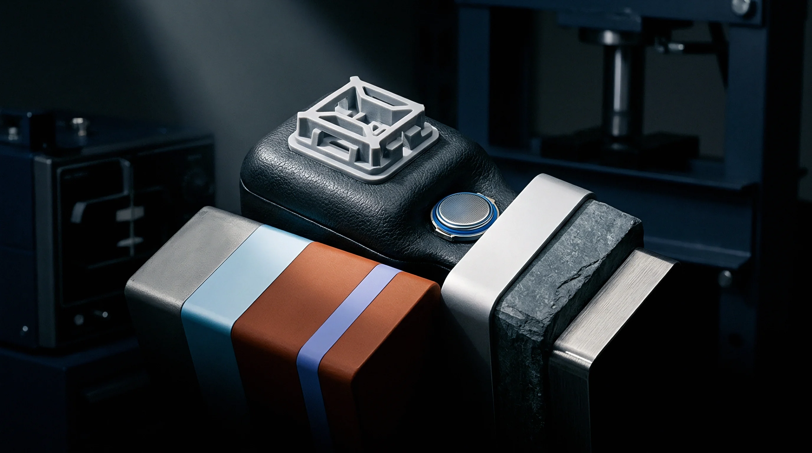
Thermal diffusion time constants scale directly with structural volume and material diffusivity. High-thermal-conductivity materials equalize localized heat injections across the payload surface, while low-expansion materials maintain spatial alignment under variable temperature profiles. Balancing structural rigidity against thermal stabilization speed defines fixture design success.
| Material Designation | Thermal Conductivity (W/m·K) | Coefficient of Thermal Expansion (ppm/K) | Specific Heat Capacity (J/kg·K) | Density (g/cm³) |
|---|---|---|---|---|
| Invar 36 (Annealed) | 10.5 | 1.2 | 515 | 8.05 |
| AlSi10Mg (Additive Powder Bed) | 130.0 | 21.0 | 910 | 2.67 |
| Titanium Grade 5 (Ti-6Al-4V) | 6.7 | 8.6 | 526 | 4.43 |
| PEEK 450CA30 (Carbon Filled) | 0.92 | 18.0 | 1150 | 1.41 |
Active compensation architectures install thermoelectric cooler elements directly behind the primary sensor mounting interface. Thermoelectric modules sink heat away from payload clusters during prolonged motor operation, pumping thermal loads to perimeter heat exchangers evacuated via liquid-cooled gimbal channels. The thermal stack includes calibrated pyrolytic graphite sheets to spread concentrated thermal points before contact with structural sub-plates.
- Structural skewing misaligns the mechanical axis of rotation from the sensor sensitive axis during continuous rotation, generating uncorrectable cross-axis acceleration components.
- Contact boundary relaxation changes spring-pin socket clamping force when thermal excursions alter retention screw tension, introducing vibration sensitivity into low-noise rate sensor data.
- Thermal mass differentials between socket bodies and sensor silicon dies cause delayed thermomechanical stress, shifting device calibration parameters outside target drift specifications.
- Platen surface convexing lifts peripheral sensor packages away from conductive heat sinks, creating twenty-degree thermal gradients between inner and outer testing rings across a single batch plate.
Baseline geometric fixture errors are frequently treated as negligible anomalies under the assumption that software polynomials absorb structural mechanics, yet polynomial correction cannot fully untangle fixture deformation from silicon drift.


Loop
Feedback architecture demands tight spatial coupling between sensor packages and compensation engines. Thermal sensors embedded inside multi-axis test carriers provide high-resolution inputs to localized proportional-integral-derivative controllers. When platinum resistance thermometers sit millimeters away from the sensor package substrate, spatial thermal lags degrade active temperature correction during rapid dynamic maneuvers.

Dynamic Compensation Pipeline Implementation
Digital sensor chips integrate internal diode temperature sensors, yet internal die temperatures reflect on-chip computation activity alongside ambient fixture changes. Dynamic active loops decouple silicon self-heating from environmental fixture shifts using multi-point state estimation.
- Multi-node temperature acquisition samples platinum resistance elements on the socket frame, carrier platen, and adjacent thermal sink surfaces at two hundred hertz synchronously with inertial sensor registers.
- Real-time state estimation computes structural gradient vectors across the fixture mounting plate using a finite-difference thermal model processed on an adjacent field-programmable gate array.
- Dynamic current adjustment drives localized thermoelectric cooler array segments via pulse-width-modulated high-frequency H-bridge drivers, counteracting measured gradient vectors.
- Sensor register correction updates dynamic polynomial compensation coefficients inside sensor non-volatile configuration memory, eliminating residual offset and sensitivity shifts.
Third-order polynomial models track steady-state uniform temperature shifts, but fail when thermal gradients sweep across the die surface at rates exceeding five degrees Celsius per minute. Active in-situ thermal stabilization clamps local socket temperature variations within plus or minus zero point zero five degrees Celsius across sixty-minute test profiles.
Closed-loop thermoelectric stabilization maintains device-under-test mounting face temperature variance within zero point zero eight degrees Celsius under thirty-degree-per-second angular velocity reversals.
| Profiling Regime | Gyroscope Bias Drift (deg/hr) | Accelerometer Bias Drift (mg) | Axis Alignment Error (arcsec) | Test Duration (min) |
|---|---|---|---|---|
| Passive Chamber Soak (Static) | 12.4 | 1.85 | 45.0 | 180 |
| Continuous Motion (Uncompensated) | 28.6 | 4.20 | 112.0 | 40 |
| Active Surface Heating (Open-Loop) | 8.2 | 1.10 | 38.0 | 40 |
| Active In-Situ Thermoelectric (Closed-Loop) | 1.5 | 0.18 | 8.5 | 45 |
The boundary between mechanical thermal lag and device internal thermal capacitance leaves the minimum attainable calibration cycle time an unresolved question for sub-millimeter wafer-scale packages.

Bus
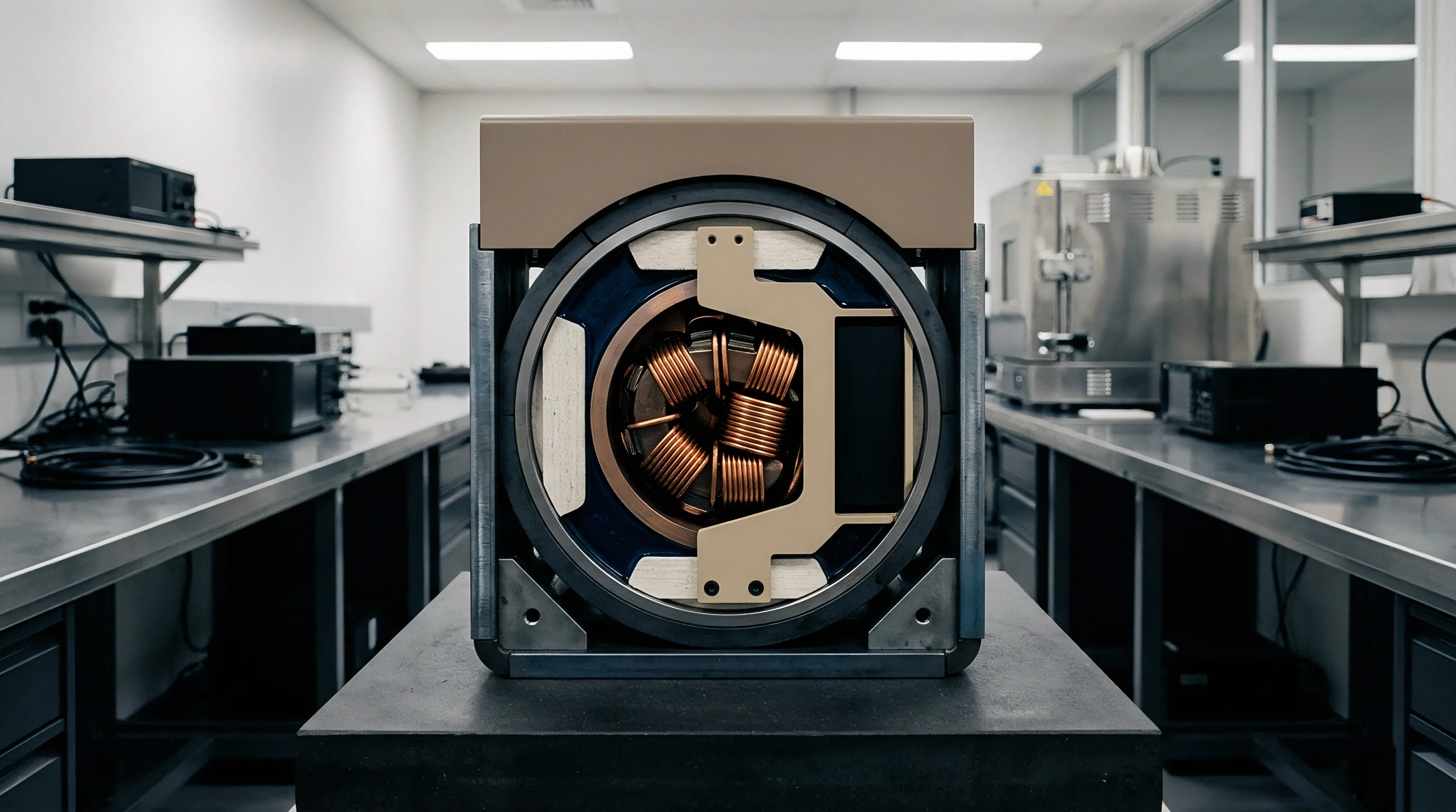
Data conveyance across rotating boundaries presents a critical electrical and thermal bottleneck. Test fixtures running continuous motion across three orthogonal axes rely on continuous-contact slip rings or high-frequency rotary transformers. Signal routing paths through slip ring assemblies pick up thermoelectric voltages generated by dissimilar metals subjected to continuous friction heating.

Does Dynamic Current Draw Corrupt Slip Ring Channels?
High-current drive lines feeding thermoelectric peltier units generate magnetic fields that couple into sensitive analog sensor output lines running through adjacent slip ring circuits. Ground loops formed between the rotating sensor head and stationary data acquisition controllers corrupt low-voltage analog sensor outputs and introduce transient errors into high-speed digital communications.
Gold-on-gold slip ring contact interfaces introduce under two microvolts of parasitic thermoelectric drift when rotational contact heating stays balanced across brush pairs.
While rotational inertia constrains response speed, separating thermoelectric power delivery channels from high-speed digital telemetry lines prevents communication bus resets during high-current cooling surges. Optical rotary joints provide complete galvanic isolation for gigabit Ethernet and serial data links, eliminating electrical noise coupling between thermal actuator power circuits and sensor measurement channels.
Clean thermal data transmission demands dedicated grounding paths isolated from actuator return currents across the entire rotating assembly.

Audit
Factory gate validation isolates systematic error. Qualification routines evaluate whether calibration errors originate within the sensor unit or stem from fixture thermal deformation under high-stress angular profiles. The validation protocol isolates sensor bias variations caused by fixture thermal expansion from true sensor thermal drift.

Chamber Dynamic Qualification Routine
Standard environmental chambers hide short-term thermal dynamics behind large internal air volumes and slow thermal response times. Validating an active in-situ fixture requires precise spatial profiling across every socket location under operational rotation.
- Mount precision three-axis reference optical mirror cubes alongside platinum resistance temperature sensors onto the active payload platen.
- Execute a three-axis continuous rotation sequence across the full angular rate band while sweeping ambient chamber conditions from minus forty degrees Celsius to eighty-five degrees Celsius.
- Record platen structural deformation continuously using external dual-wavelength autocollimators aligned through optical chamber access ports.
- Compare structural platen distortion against registered sensor thermal compensation data to calculate fixture-induced measurement uncertainty.
Fixture validation documents must establish clear boundaries of measurement uncertainty, confirming that platen warping remains below five arcseconds across the complete testing temperature spectrum. Incomplete qualification data risks transferring fixture geometric distortions into downstream embedded firmware tables.
Engineering teams validating production runs maintain baseline laser metrology data for every manufactured fixture head, checking spatial alignment quarterly to catch mechanical wear before it influences device calibration parameters.


Dossier
The technical data package establishes legal boundaries between buyer and manufacturing integrator. When sourcing turnkey multi-axis testing fixtures, ownership of internal controller source code, thermal simulation decks, and mechanical fabrication drawings determines system maintainability. Ambiguity regarding who manages thermal calibration firmware updates locks buyers into single-vendor maintenance contracts.

Procurement Scope and Engineering Allocation
Disagreements arise when delivery specifications omit acceptance tests under active rotation and thermal loading. Turnkey fixture providers frequently validate mechanical rate tables at static room temperatures, shifting dynamic thermal integration burdens to the buyer bring-up team.
| Engineering Domain | Turnkey Purchase | Semi-Custom Build | Reference Design Transfer |
|---|---|---|---|
| Thermal Modeling Files | Compiled Binaries Only | Validated Finite Element Decks | Uncalibrated Reference Geometries |
| Control Loop Firmware | Pre-programmed Microcontroller | Documented C Source and Header Files | Vendor Sample Code |
| Slip Ring Interface Board | Tested Assembled Hardware | Gerbers, Schematics, and Drill Files | Reference Layout Guide |
| Calibration Certificate | Factory Standard Pass/Fail | Dynamic Uncertainty Matrix | None Provided |
| Non-Recurring Engineering Fee | Zero Direct NRE | Forty to Eighty Thousand USD | Internal Development Absorption |
Procurement documents protect product margins when contract statements explicitly state acceptance criteria based on operational temperature stability rather than passive thermal equilibrium. Statements of work that stipulate delivery of uncompiled finite element models and low-level actuator firmware allow buyers to re-tune active loops as production sensor silicon revisions change package thermal dynamics.
Section 4.2 of the standard equipment fabrication agreement establishes that failure of the active platen to maintain thermal stability within zero point one degrees Celsius under dynamic rotation constitutes a non-conforming build, permitting full withholding of final integration milestone payments.