Statistical Gage Repeatability Verification Standards for Relocated Production Fixtures
Relocating production fixtures mandates statistical gage re-verification via ANOVA Gage R&R and Type I studies to prove repeatability under new plant dynamics.

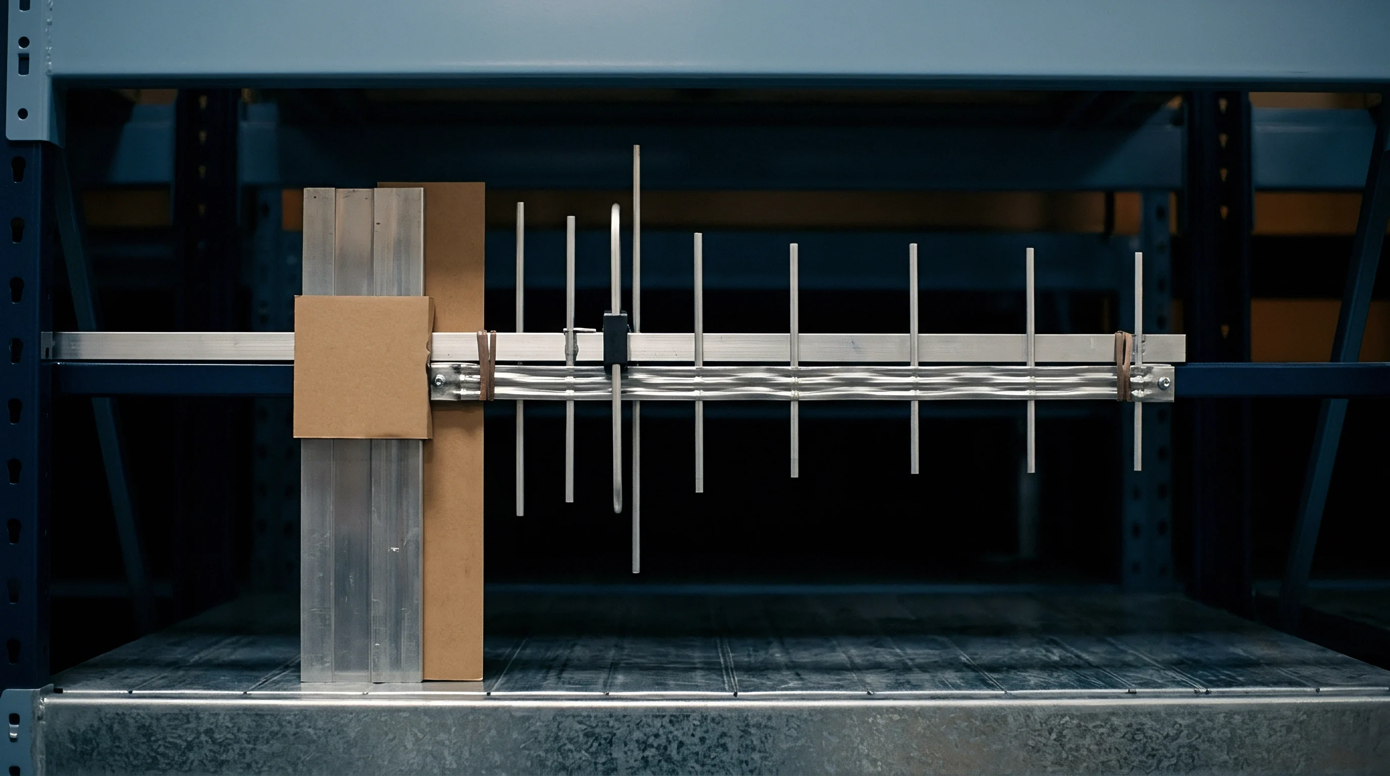
Transit
Transporting an inspection assembly releases stresses locked into welded frames, ground tool steel plates, and mechanical linkages during fabrication. Shipping a multi-cavity dimensional fixture across long distances subjects it to sustained low-frequency shock, vibration, and sharp temperature swings. Ocean containers see random multi-axis vibration from 2 to 200 Hertz alongside deck temperature swings from sub-zero conditions to 60 degrees Celsius.
These forces shift the micro-geometry of the gage before the crate reaches the receiving dock.
As metrology fixtures travel between facilities, distortion accumulates across joints, dowel pins, and threaded fasteners. Cast tooling plates such as MIC-6 aluminum expand at roughly 23 micrometers per meter per degree Celsius, while structural steel sub-bases expand at about 12 micrometers per meter per degree Celsius. A two-meter hybrid steel-and-aluminum fixture subjected to a 40-degree transit gradient expands unevenly across its frame.
This mismatch places threaded fasteners in shear, forces ground locating pins against press-fit bores, and leaves residual mechanical strain trapped once temperatures normalize.
Receiving plant environments rarely mirror the origin facility. Slab thickness, foundation dampening, grounding quality, and local HVAC drafts all affect fixture behavior. Anchoring a relocated gage onto a four-inch unreinforced slab next to a 500-ton stamping press introduces micro-deflections during measurement cycles, compromising repeatability before the first part is even loaded.

Mechanics of Structural Distortion in Transported Measuring Apparatus
Dynamic transit loads alter settled mechanical interfaces. Threaded connections without positive locking hardware slip under sustained vertical acceleration peaks over 3 gravity units. Dowel pins press-fitted into aluminum plates with light interference fits creep under cyclic shear loads.
A shift in locating pin position of just 3 micrometers moves the nest’s geometric center relative to fixed sensor points.
Tactile air-gage nozzles, LVDTs, and optical mounts easily shift out of true under transit shocks. Dial indicator stems and electronic slides bind if transport locks are disengaged during shipping. Internal springs yield, bearing tracks develop fretting wear from constant vibration, and pre-loads fall below calibrated thresholds.
The table below outlines common failure modes across transport modes when fixtures move without dedicated shipping locks and environmental isolation.
| Transport Mode | Dominant Physical Vector | Primary Failure Mode | Dimensional Deviation Range | Gage Performance Impact |
|---|---|---|---|---|
| Air Freight | High-frequency turbine vibration and rapid barometric pressure shifts | Pneumatic seal creep and diaphragm displacement in air-actuated nests | 2 to 5 micrometers | Shift in zero-point calibration; elevation of baseline measurement drift |
| Ocean Container | Low-frequency hull roll and severe ambient thermal cycling | Differential thermal expansion stress relief; surface corrosion on ground datums | 12 to 35 micrometers | Severe bias shift; loss of part seating parallelism across primary reference plane |
| Standard LTL Trucking | Impact shock from spring suspension over road joints | Dowel pin shear migration and loosening of bolted frame joints | 8 to 20 micrometers | Degradation of repeatability; increase in equipment variation component |
| Air-Ride Transport | Low-amplitude continuous harmonic resonance | Fretting corrosion on ball slides and contact tip flat-spotting | 1 to 4 micrometers | Elevated micro-hysteresis during probe approach cycles |
Vacuum and pneumatic clamping nests frequently suffer seal degradation during relocation. Elastomeric seals harden during extreme container temperature cycles and lose elasticity. Once hooked to plant air at the new site, leaking seals drop holding force.
Unstable clamping pressure causes variable part deflection during measurement, registering in software as false part instability.
Unpassivated tool steel datums, ground blocks, and ball-nested rest buttons oxidize rapidly in humid shipping environments. Ocean freight without vapor-corrosion-inhibitor packaging develops oxide films between 1 and 5 micrometers thick. These surface layers prevent workpieces from seating flush against primary datums, introducing a constant dimensional bias across every feature measured.

Environmental Thermal Shifts and Stress Relief Behaviors
Internal stress in welded steel frames relaxes during thermal cycling. Frames fabricated without thermal or mechanical stress relief warp when shipping temperatures exceed 50 degrees Celsius. As the structure moves, opposing measurement points lose alignment relative to one another.
Fixture relocation exposes latent internal stress that previously remained hidden under controlled room temperatures.
Machined components experience micro-structural relaxation when thermal swings overcome joint friction. A baseplate torque-checked at 21 degrees Celsius redistributes its bolt tension when chilled to minus 15 degrees in an aircraft hold and then brought onto a tropical dock at 35 degrees. This shift in clamping tension permanently alters baseplate flatness.
Transit shocks and thermal swings degrade optical fixtures through misaligned mirrors and skewed laser lines. Brackets securing cameras, telecentric lenses, and laser projectors expand and contract at different rates. Angular shifts of just a few arcseconds at the mount produce spatial offsets of tens of micrometers at the focal plane, invalidating factory calibration.
- Kinematic Pin De-alignment occurs when high lateral transport shock shifts press-fit locating pins beyond two micrometers, altering part datum registration against fixed sensor heads.
- Baseplate Warp Relief manifests when internal residual stress relaxes during temperature cycles inside shipping containers, permanently twisting planar reference surfaces.
- Pneumatic Clamping Hysteresis develops when altered plant air regulator line pressures alter cylinder seating dynamics, creating inconsistent part deformation during measurement.
- Tactile Probe Deflection occurs when transit locking brackets fail to decouple load cell linkages during freight vibration, damaging internal spring mechanisms.
Sub-base compliance causes long frames to deflect under their own weight. A three-meter fixture qualified on an eight-inch reinforced slab will sag when anchored to a thinner floor. Unsupported spans drop under gravity, introducing angular runout along primary axes.
Leveling feet without load cell balance transfer local floor irregularities straight into the gage structure.
Software offsets cannot correct baseline structural distortion. Shifting digital zeros to mask physical datum movement merely conceals geometric tilt. As production parts vary within tolerance, a tilted nest will trigger false rejects or accept out-of-spec parts.
Recovering measurement integrity requires mechanical realignment, stress relief, and establishing physical zero before running statistical qualifications.
Discrepancies in lower baseplate three-point calibration often trace back to shop-floor slab resonance at the receiving plant rather than structural failure in the fixture frame.


Arithmetic
Statistical qualification confirms whether a relocated gage can distinguish genuine part variation from measurement noise. Routine calibration checks fail to capture interactive variables like clamping force, ambient temperature drifts, and mechanical hysteresis. A proper gage study isolates these variance components using decomposition models that evaluate the system against both part tolerance and overall process spread.
Qualification begins by evaluating resolution, bias, and repeatability against reference standards before moving to multi-operator production trials. Relocating a gage introduces new thermal profiles, altered foundation dynamics, and different operating habits, all of which directly increase the Equipment Variation and Appraiser Variation metrics defined by AIAG standards.

Type I Studies for Relocated Reference Standards
Repeatability and bias validation requires a certified reference master traceable to national metrology institutes. An operator cycles the master into the relocated nest 50 consecutive times under fixed settings, recording the readout on each pass. This Type I Gage Study separates baseline gage mechanics from operator influence.
The Type I capability index (Cg) evaluates the gage’s spread across the 50 runs relative to the part tolerance band, comparing six standard deviations of measurement error against 20 percent of total tolerance:
Cg = (0.20 Tolerance) / (6 S_sample)
Here, S_sample is the standard deviation across all 50 master readings. A Cg of 1.33 or greater demonstrates that the relocated fixture has sufficient short-term repeatability to proceed to operator testing.
The Cgk index incorporates systematic measurement bias by comparing the sample mean against the master artifact’s certified dimension:
Cgk = (0.10 Tolerance – |X_bar – Reference_Value|) / (3 S_sample)
Where X_bar is the mean of the 50 measurements and Reference_Value is the known size of the standard. A Cgk below 1.33 flags calibration drift or mechanical seating errors, requiring physical correction before measuring production parts.
Type I studies quickly surface physical issues from shipping, like worn probe tips, loose indicators, or fluctuating air pressure. If Cg drops below 1.33 on a solid steel master, running a full Gage R&R will only generate noisy data and waste floor time.

ANOVA Variance Component Breakdown versus Range Methods
Assessing fixture performance across multiple operators and production samples requires Analysis of Variance (ANOVA) rather than the simplified Average and Range method. Average and Range techniques assume no interaction between operators and parts, overlooking seating inconsistencies that only occur when particular operators clamp specific part shapes. ANOVA splits total variation into clear components: Part-to-Part, Equipment, Appraiser, and Appraiser-by-Part Interaction.
Running an ANOVA Gage R&R requires 10 production samples covering the full tolerance range. Three trained operators run each sample 3 times in random sequence, producing 90 discrete data points. The two-way ANOVA model breaks down the total sum of squares:
Var_Total = Var_Part + Var_Equipment + Var_Appraiser + Var_Interaction
Equipment Variance reflects pure gage repeatability and structural rigidity. Appraiser Variance captures reproducibility differences in part loading and clamping habits. Appraiser-by-Part Interaction flags instances where an operator’s clamping style flexes non-rigid workpieces against the datums.
| Statistical Metric | Mathematical Formula / Origin | Acceptable Threshold | Conditional Limit | Action Required if Failed |
|---|---|---|---|---|
| Type I Capability (Cg) | (0.20 Tolerance) / (6 S_sample) | Cg >= 1.33 | 1.00 <= Cg < 1.33 | Re-align probe mounts; replace worn locating pins; overhaul mechanical slide stops |
| Type I Bias Capability (Cgk) | (0.10 Tol – |X_bar – Ref|) / (3 S_sample) | Cgk >= 1.33 | 1.00 <= Cgk < 1.33 | Re-zero master baseline; adjust physical datum location offset in measurement controller |
| Percent Gage R&R (%GRR) | (SD_Gage / SD_Total) 100 | %GRR < 10% | 10% <= %GRR <= 30% | Implement mechanical part guides; automate clamping pressure; re-train operators |
| Tolerance Consumption (%P/T) | (6 SD_Gage / Tolerance) 100 | %P/T < 10% | 10% <= %P/T <= 30% | Refine fixture geometry; upgrade displacement sensors to higher resolution units |
| Number of Distinct Categories (ndc) | 1.41 (SD_Part / SD_Gage) | ndc >= 5 | ndc = 4 | Reject measurement system; select higher discrimination instrumentation |
The combined Gage R&R standard deviation (SD_Gage) aggregates Equipment, Appraiser, and Interaction terms:
SD_Gage = Square_Root(Var_Equipment + Var_Appraiser + Var_Interaction)
Percent Gage R&R (%GRR) relates this combined standard deviation to the total process standard deviation or product tolerance. Fixtures yielding a %GRR below 10 percent pass immediately. Values between 10 and 30 percent are conditionally acceptable based on process criticality and quality agreements.
Anything over 30 percent indicates an incapable measurement setup that cannot reliably accept or reject parts.
A measurement system with percent GRR below ten percent consumes less than three percent of the total engineering tolerance band during high-volume acceptance testing.
The Number of Distinct Categories (ndc) indicates how many distinct measurement intervals the fixture can separate across the part distribution. The value is rounded down to an integer:
ndc = 1.41 (SD_Part / SD_Gage)
Automotive and aerospace quality standards require an ndc of 5 or higher. An ndc below 5 turns the setup into a basic go/no-go gage, losing the ability to track continuous process trends. Low ndc values point to inadequate sensor discrimination or high fixture noise masking actual part differences.
Executing the statistical qualification sequence follows a strict sequence during plant line bring-up.
- Select ten production parts spanning eighty percent of the full manufacturing tolerance range from normal production runs.
- Calibrate three operators on fixture clamping mechanisms and part seating procedures using identical torque specifications.
- Execute thirty randomized measurement trials per operator across three non-consecutive shifts to capture environmental swings.
- Decompose total observed variance into equipment, appraiser, and part-to-part interaction components using two-way ANOVA.
- Compute the number of distinct categories to verify measurement system discrimination power exceeding five distinct bands.
The variance ratios reveal where mechanical faults originate. Elevated Equipment Variance indicates physical wear, loose slides, or sensor drift. High Appraiser Variance points to improper part loading, inconsistent clamping torque, or readout parallax.
High Interaction Variance means operator clamping technique deforms parts unevenly, suggesting a need for regulated pneumatic or hydraulic clamping.
The remaining uncertainty is whether short-term statistical repeatability achieved during initial three-shift trials holds up when seasonal temperature swings alter plant slab dimensions over six months of operation.


Clamp
Proper mechanical alignment underpins all statistical repeatability. A heavy base frame will still generate poor Gage R&R numbers if clamps apply inconsistent force vectors against the datums. Commissioning tooling after transit requires systematic realignment of kinematic points, regulated clamping forces, and adequate thermal stabilization before zeroing the instrumentation.
Kinematic design principles dictate how fixtures support parts without over-constraint or induced bending moments. The primary datum uses three contact points to define a reference plane, the secondary uses two to form an axis, and the tertiary uses one as a stop. If transit impacts move any of these six contact points, part seating becomes inconsistent in ways that digital calibration cannot overcome.

Kinematic Location and Datum Alignment Mechanics
Restoring datum locations requires mapping locating pins against fixture datums using a portable CMM or laser tracker. Sphere-mounted retroreflectors track spatial errors introduced during shipping. Ground spherical locating pins must remain square to mounting faces within 5 micrometers per 100 millimeters of runout.
Replacing worn or damaged dowel pins calls for tool steel or carbide pins ground to a finish below Ra 0.2 micrometers. Driving interference pins in with a hammer distorts surrounding metal and tilts the pin axis. New pins should be seated using pulling screws or thermal shrinking, chilling the pins in liquid nitrogen before insertion into precision reamed bores.

How Does Mechanical Hysteresis Degrade Dynamic Repeatability?
Worn pivot bushings introduce clamping hysteresis by allowing clamp arms to track inconsistently across cycles. When a pneumatic clamp swings freely through an unguided arc, pivot play shifts where the clamp pad makes contact. Shifting contact points by only 3 millimeters from the supported datum generates cantilever moments that deflect measured surfaces by several micrometers.
Measuring hysteresis requires placing displacement indicators on clamp arms to track touchdown points across 50 consecutive cycles. If contact position varies by more than 15 micrometers, pivot bushings must be replaced with zero-clearance, preloaded needle bearings. Clamping forces must drive workpieces directly into primary stops without generating shear loads across secondary datums.
Regulating clamping force is critical on sheet metal, thin-wall aluminum, and injection-molded plastic parts that flex under pressure. Manual toggle clamps depend entirely on operator feel, inflating appraiser variation in Gage R&R studies. Switching to pneumatic cylinders controlled by precision regulators maintains clamping force within 1 percent cycle after cycle.
Torque-limiting wrenches provide a reliable alternative where pneumatic clamps are impractical. Torquing manual hold-downs to fixed values ~ such as 4.5 Newton-meters on light aluminum housings ~ keeps operators from over-tightening bolts and distorting the nest. These torque tools should be checked daily against load cell testers.
Fixtures anchored to uninsulated plant floors follow ground ground-swelling cycles that corrupt precision measurements.
Thermal equalization prevents mechanical distortion when transferring tooling between environments. Bringing a fixture from a winter freight bay into a humid 24-degree shop floor causes rapid condensation and uneven thermal expansion. Outer baseplate sections expand while internal steel cores stay cold, twisting reference planes.
Fixtures need at least a 12-hour thermal soak in the metrology area to bring internal temperatures within 0.5 degrees Celsius of ambient air. Thermocouple logs on the thickest plate sections confirm thermal equilibrium before shipping brackets are removed or datums are adjusted.
Systematic verification prevents premature statistical testing on unstable mechanical setups.
- Datum Pin Verification mandates three-axis laser tracker inspection of ground locating pins prior to initial part loading.
- Torque Multiplier Calibration requires pneumatic and manual torque wrenches verified against certified load cell standards.
- Thermal Soak Isolation prescribes twelve hours of unencumbered soak time inside the receiving facility prior to mechanical re-anchoring.
- Pneumatic Seating Confirmation uses back-pressure sensors to confirm flush workpiece contact against hard stops before measurement cycles trigger.
Air-gap back-pressure sensors confirm whether workpieces sit flat on primary datums. Fixtures incorporate tiny air orifices inside ground rest pads, feeding low-pressure air across the contact area. When parts seat correctly, back-pressure climbs toward supply pressure and trips the green indicator.
If chips, chips, or burrs hold the part off the pad by 2 micrometers, air escapes, pressure drops, and the controller locks out the cycle.
When kinematic locating pins show visible fretting wear, replacing them precedes any attempt to resolve statistical variation through mathematical offsets.


Audit
Quality management systems govern tooling transfers through formal validation procedures. Moving a dimensional fixture resets its Measurement System Analysis approvals under international automotive and aerospace regulations. Returning a gage to service requires re-establishing traceability, repeating statistical studies, and securing formal engineering sign-off before measuring production parts.
IATF 16949 Section 7.1.5 treats transferred gages as new equipment. Facilities must demonstrate unbroken traceability to national standards, maintain calibration schedules, and update measurement uncertainty budgets. Running relocated tooling without refreshed MSA studies leads to major non-conformances during compliance audits.

Quality Management System Requirements for Tooling Transfer
Tool transfer records begin with the formal relocation authorization. Quality engineers compile baseline data from the shipping plant, including historical Gage R&R files, master part certification sheets, and current part print revisions. These records set the benchmark that the fixture must meet at the receiving plant.
Receiving inspection follows standard equipment intake routines. Inspectors examine freight crates for tripped shock or tilt indicators. After uncrating, technicians inspect ground datums for mechanical damage or oxidation and verify all loose accessories against the bill of materials.
These initial visual and dimensional checks start the re-qualification dossier.
| Standard / Regulation | Clause Reference | Mandated Verification Activity | Required Documentation Output | Non-Compliance Penalty |
|---|---|---|---|---|
| IATF 16949:2016 | 7.1.5.1.1 Gage Studies | Statistical verification of all relocated measurement systems prior to production release | ANOVA Gage R&R study report with %GRR < 10% and ndc >= 5 | Immediate invalidation of Production Part Approval Process (PPAP) status |
| IATF 16949:2016 | 7.1.5.2 Traceability | Calibration traceability to national or international standards (NIST, PTB) | Traceable calibration certificates for reference masters and internal sensors | Major non-conformance during customer or registrar quality audits |
| AIAG MSA 4th Edition | Chapter III Section B | Variance component analysis covering Equipment, Appraiser, and Interaction effects | Type I Gage Study (Cg/Cgk) and two-way ANOVA decomposition worksheets | Rejection of measurement capability during customer quality gate reviews |
| ISO/IEC 17025:2017 | 6.4 Equipment Control | Re-verification of measuring equipment accuracy following transport or maintenance | Uncertainty budget calculation covering environmental and mechanical factors | Loss of accredited testing scope for receiving plant metrology lab |
Traceability requires linking fixture readouts back to national standards via an unbroken chain of accredited calibration records. If master artifacts travel with the fixture, an accredited laboratory must recalibrate them to ensure transit stresses caused no dimensional changes. Using unverified masters to certify relocated tooling breaks metrological traceability.
Updating the fixture’s uncertainty budget requires incorporating ambient and mechanical variables into the expanded uncertainty model. Combined standard uncertainty accounts for master calibration limits, thermal differences, gage resolution, and repeatability variance:
U_combined = 2 Square_Root(u_master^2 + u_thermal^2 + u_resolution^2 + u_repeatability^2)
Here, u_master comes from the master certificate, u_thermal reflects temperature stability at the new plant, u_resolution accounts for sensor discrimination, and u_repeatability equals the Equipment Variation standard deviation from ANOVA trials. Applying a coverage factor of k = 2 establishes a 95 percent confidence interval across measured dimensions.

Design Transfer Dossier Structure for Re-Qualification
The design transfer dossier compiles all technical validation data from original CAD prints through final MSA sign-off. Quality management approves this dossier before releasing the gage to inspect production parts. Incomplete dossiers delay customer part approval and hold up commercial production.
Clause 7.1.5.2 of IATF 16949 invalidates production part approval process sign-offs whenever measurement equipment relocates without documented re-calibration and statistical verification.
Revision management prevents mismatches between parts and inspection tools. A fixture built to revision A prints will reject good components if the new facility manufactures to revision C. Nest details, probe locations, and program limits must be updated to match the active part revision before running statistical trials.
The re-qualification dossier must organize technical records into discrete, auditable sections.
- Baseline Master Calibration Certificates provide traceable dimensional proofs from accredited metrology laboratories performed immediately prior to pack-out.
- Statistical Re-qualification Reports deliver raw measurement data, ANOVA variance component tables, and capability indices signed by plant quality managers.
- Preventive Maintenance Schedules outline wear-item replacement intervals, torque re-check cadences, and daily zero-point check instructions.
- Operating Procedure Revisions document updated clamping forces, cleaning steps, and environmental limits specific to the destination plant layout.
Storing raw statistical data in central quality databases ensures long-term accessibility. Keeping individual measurement runs alongside high-level summaries allows quality teams to recalculate capabilities if customer evaluation methods change. Retaining original sensor calibration curves and metrology routines ensures complete traceability across the equipment’s lifespan.
Section 7.1.5.1.1 of the IATF 16949 standard requires suppliers to retain complete statistical measurement system analysis records for all relocated tooling, shifting liability directly onto the plant manager who approves line transfers without re-qualification data.


Margin
Relocating inspection fixtures carries significant labor costs, equipment expenses, and operational risks. Treating tooling transfers as simple freight moves leads to cost overruns when gages fail initial site qualification. Realistic project budgeting includes laser tracker alignment, metrology support, operator retraining, and downtime buffers during recommissioning.
Financial exposure during line relocations usually comes from unplanned metrology rework and delayed PPAP sign-offs. Line downtime expenses running thousands of dollars per hour quickly exceed the direct freight cost of the tooling. Defining clear scopes of work, setting vendor responsibility boundaries, and budgeting for complete qualification preserves project margins.

Financial Structure of Measurement Tooling Relocation
Calculating the true cost of tooling transfers requires budgeting across six distinct phases: decommissioning, export crating, transit, mechanical re-installation, datum restoration, and statistical qualification. Cutting corners during prep and crating simply multiplies expenses later, as repairing structural distortion on an active plant floor costs three times as much as proper shop prep.
Contracted metrology services make up a large portion of bring-up costs. Certified technicians with laser trackers or portable CMMs bill at 150 to 250 dollars per hour. A complex multi-station fixture typically requires 30 to 50 engineering hours to map datums, adjust locating pins, set sensor baselines, and complete Type I studies.
The financial model below details typical non-recurring engineering and operational expenses absorbed during a cross-border fixture relocation program involving three multi-station dimensional inspection nests.
Origin Facility De-commissioning and Master Calibration ~ $12,500 Includes baseline laser tracker mapping, calibration of reference master artifacts at an accredited laboratory, transit brace installation, and climate-controlled packing.
Air-Ride Specialized Transport and Logistics ~ $8,200 Covers dedicated air-ride freight transport with temperature logging instrumentation and full transit insurance coverage up to five hundred thousand dollars valuation.
Mechanical Re-anchoring and Floor Slab Preparation ~ $14,800 Covers core drilling, installation of vibration-isolated floor mounting plates, precision leveling, thermal stabilization dwell periods, and pneumatic supply regulation upgrades.
Destination Engineering Bring-Up and Metrology Labor ~ $22,500 Encompasses ninety hours of certified metrology engineer time for mechanical datum alignment, probe tip replacement, software routine updating, and baseline zero setup.
Statistical Re-qualification Execution ~ $16,200 Covers plant operator training, collection of ninety-point ANOVA trial data sets, production sample verification, and assembly of final IATF 16949 qualification dossiers.
Unplanned Qualification Downtime Contingency (15%) ~ $11,130 Allocated reserve fund covering secondary mechanical adjustments, pin replacement re-runs, or secondary statistical trials if initial %GRR exceeds acceptance limits.
Total Program Non-Recurring Engineering Cost ~ $85,330
Investing ten thousand dollars in pre-shipment structural bracing and baseline CMM mapping reduces average metrology bring-up time at the receiving facility from fourteen business days down to three business days.

Contractual Risk Allocation and Responsibility Boundaries
Relocation contracts must establish clear technical divisions between equipment buyers, freight carriers, and plant operations. Statements of work that generically call for the vendor to “relocate and commission” tooling fail to define who bears the cost if ambient factory conditions prevent a fixture from passing a 10 percent GRR threshold.
Clear contract boundaries separate intrinsic fixture capability from operational variables. The statement of work should require the vendor to guarantee Type I Cg values of 1.33 or higher on certified masters under controlled temperatures. If high Appraiser Variation or floor vibration degrades overall %GRR during operator trials, responsibility for dampening and training falls on plant management.
Engineering change controls should cover any fixture rework during the move. Modifying mechanical tooling to suit drawing revisions while in transit requires formal change documentation. Mixing engineering changes with a physical move muddies the cause of qualification failures, making it difficult to distinguish transit damage from unvalidated nest modifications.
Turnkey relocation agreements need enforceable exit clauses. A 30-day qualification window from equipment arrival ensures project teams can intervene if tooling fails acceptance tests. The contract should allow the buyer to bring in third-party metrologists at the vendor’s expense if the vendor cannot bring %GRR under 30 percent within 30 calendar days of installation.
An uncalibrated pneumatic clamping regulator on an engine module tooling transfer risks three-day delays in customer PPAP sign-off and forty-two thousand dollars in line-stoppage penalties.