Meaning
Systematic shifting of the calculated energy center of an optical beam or particle distribution across an array sensor under varying physical conditions introduces positional measurement inaccuracies. The phenomenon of spatial centroid walking occurs when optical power fluctuations, thermal expansion gradients, detector gain non-uniformities, or changing incidence angles move the calculated peak energy point away from the true mechanical axis. This displacement degrades tracking accuracy in free-space optical transceivers, laser profiling systems, and position-sensitive tracking architectures.
The metric stops representing physical alignment drift if optical sensor saturation clips the energy profile, generating artificial centroid calculations from flat-topped intensity distributions.
Thermal Gradients
Differential thermal expansion inside optical lens mounts or sensor packages displaces the optical axis relative to the active silicon matrix. As local internal heat sources warm the mechanical chassis non-uniformly, spatial centroid walking manifests as continuous sub-micron position drift over extended operational windows. Low-expansion housing alloys like Invar or regulated active thermal heating loops stabilize the optomechanical relationship against changing external temperatures.
Thermal dissipation modeling confirms structural mechanical stability across the product lifecycle.
Detector Asymmetries
Responsivity variances across adjacent sensor pixels distort the computed center of gravity of an incident symmetric beam profile. When energy sweeps across silicon regions with differing quantum efficiencies, the computational centroid algorithm shifts toward the higher-gain pixels. Calibration maps stored in non-volatile memory counteract this effect by applying flat-field gain corrections to raw intensity values before centroid computation.
Anti-blooming circuitry protects adjacent pixels from charge spillage that would bias position calculations during local over-exposure events.
Calibration Verification
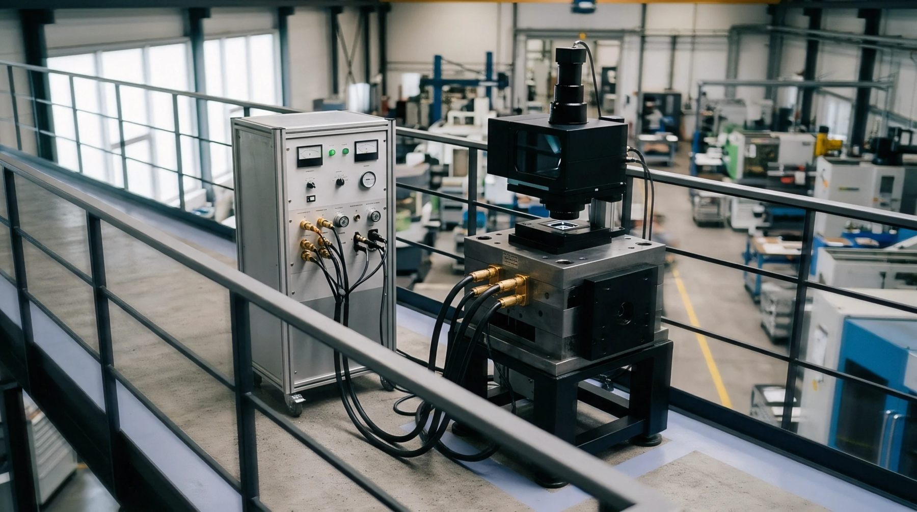
Environmental chambers house optomechanical assemblies under dynamic temperature and input flux stress to quantify centroid deviation against reference multi-axis retroreflectors. Automated logging software monitors calculated beam positions, plotting drift vectors across operational extremes. The final thermal-optical calibration report records peak centroid wander across designated angle and temperature boundaries, confirming sensor adherence to industrial pointing tolerances.
This verification file must accompany finished assemblies for high-precision optical tracking applications.