Optimizing Dynamic Real Time Clock Temperature Compensation Intervals in Sub-GHz Mesh Networks
Dynamic RTC temperature compensation adjusts sampling rates based on thermal derivatives, reducing mesh guard-band energy consumption while holding timing lock.


Drift

Sub-GHz Mesh Slot Timing Boundaries
Frame synchronization in Time-Slotted Channel Hopping networks requires precise timekeeping across distributed nodes. Sub-GHz protocols operating in the 868 MHz and 915 MHz bands, such as IEEE 802.15.4g and Wi-SUN FAN, divide channel access into deterministic time slots, typically between 10 milliseconds and 50 milliseconds long. Within a slot, the transmitter emits a physical layer preamble at a designated offset while the receiver opens a window to capture the packet.
Timing misalignment between them forces the network layer to widen receiver windows or drop frames altogether.
Outdoor sub-GHz links can stretch over two kilometers, adding roughly 3.3 microseconds of propagation delay per kilometer to the timing budget. Slot timing budgets allocate fixed microsecond tolerances across crystal drift, propagation delay, and RF synthesizer lock times. If cumulative clock skew outstrips the guard band, the receiver misses the packet preamble.
Recovering synchronization requires explicit beacon exchanges, spending battery power and creating extra channel overhead across the mesh.
Root nodes establish master timing, distributing absolute slot numbers in periodic frame synchronization headers. Child nodes calculate their offset against the parent clock on each successful frame exchange. In low-duty-cycle networks, nodes sleep between communication windows to save power ~ sometimes for seconds, sometimes for tens of minutes ~ which magnifies the effect of uncompensated clock drift.
A standard 32.768 kHz tuning-fork crystal exposed to a 15 degrees Celsius thermal shift without compensation accumulates 12.4 microseconds of timing skew across a 10-second Time-Slotted Channel Hopping frame interval.

Parabolic Crystal Frequency Characteristics
Standard 32.768 kHz tuning-fork quartz crystals show a quadratic frequency shift as ambient temperature changes. The frequency deviation depends directly on how far the operational temperature sits from the turnover point, which typically centers at 25 degrees Celsius where deviation is zero. The parabolic temperature coefficient for these crystals is minus 0.034 parts per million per degree Celsius squared.
At 25 degrees Celsius, the crystal runs at nominal frequency, but at minus 40 degrees Celsius or positive 85 degrees Celsius, uncompensated frequency error reaches roughly minus 143 parts per million. That translates directly to 143 microseconds of clock drift every second. Over a 60-second sleep interval, an uncompensated node drifts by more than 8.5 milliseconds, blowing past standard time-slot guard bands.
Integrated real-time clock modules use internal capacitive tuning arrays to offset this parabolic drift. By writing digital values to a compensation register, the clock controller alters load capacitance to nudge the oscillator back toward nominal frequency. Polling an onboard temperature sensor updates this calibration register.
Without these regular adjustments under changing outdoor conditions, nodes suddenly drop off the mesh and trigger continuous repair sweeps that can drain primary lithium batteries in weeks.


Ramp

Thermal Derivative Sensing Architecture
Local thermal gradients determine how often an embedded microcontroller should update its real-time clock calibration register. Sampling temperature at fixed intervals ~ say, every 60 seconds ~ works in stable conditions but falls behind during rapid thermal ramps. Direct solar exposure, wind gusts, cold rain, or industrial HVAC cycling introduce fast environmental transitions that can double frequency shifts.
In outdoor deployments, morning sun hitting a dark enclosure can drive thermal ramps of 5 degrees Celsius per minute. Polling every 60 seconds under those conditions leaves the real-time clock running on stale compensation factors for the entire interval, accumulating drift that quickly exceeds standard 1-millisecond receiver guard bands.
Dynamic compensation architectures calculate the first derivative of temperature over time. By tracking consecutive readings, the microcontroller evaluates the rate of change between samples. When the absolute rate stays below 0.1 degrees Celsius per minute, the controller stretches the sampling interval to save power; as temperature changes accelerate, it shortens the interval accordingly.
Thermal mass variations between outer plastic enclosures and internal PCB ground planes introduce thermal lag during sudden ambient air transitions.

Mathematical Formulation of Variable Calibration Rates
Calculating the time derivative of local temperature measurements allows firmware to dynamically scale the polling timer. Firmware defines a baseline sampling interval, designated as T-base, for thermally stable periods. An internal algorithm takes the absolute difference between current and previous temperature samples and divides it by elapsed time to find the instantaneous ramp rate.
The interval controller then scales the next sample delay using an inverse proportional relationship bounded by minimum and maximum limits.
| Compensation Strategy | Temperature Polling Interval | Clock Drift at 5°C/min Ramp | Radio Guard Band Allowance | Monthly Battery Drain Contribution |
|---|---|---|---|---|
| Fixed Static Polling | 60.0 Seconds | 4.20 Microseconds / Second | 1000 Microseconds | 0.42 Milliampere Hours |
| Linear Slope Scaling | 10.0 to 60.0 Seconds | 1.85 Microseconds / Second | 600 Microseconds | 0.68 Milliampere Hours |
| Thermal Derivative (dT/dt) Adaptive | 1.0 to 120.0 Seconds | 0.35 Microseconds / Second | 200 Microseconds | 0.31 Milliampere Hours |
Implementing dynamic compensation requires systematic steps within the real-time clock firmware stack:
- Initialize hardware timers to trigger low-power analog-to-digital conversions on the internal temperature sensor channel at the baseline interval.
- Read the temperature sensor output voltage and convert the raw digital code into a calibrated temperature value stored in system RAM.
- Compute the thermal derivative by subtracting the prior sample temperature from the current reading and dividing by the elapsed sample duration.
- Evaluate the derivative threshold against predefined execution boundaries to determine whether the thermal gradient requires faster sampling.
- Recalculate capacitive tuning load register values using the manufacturer crystal parabolic formula combined with calibrated factory offsets.
- Update the real-time clock compensation register via SPI or I2C bus write cycles before returning the processor to ultra-low-power sleep mode.
Internal temperature sensors are often described as providing automatic crystal compensation without external software intervention, yet datasheet specifications assume constant room temperature during factory calibration sweeps.


Guard

Receiver Listening Window Budgeting
Widen the preamble listening window and you absorb timing skew, but at the expense of battery capacity. In a Time-Slotted Channel Hopping network, the receiver powers up its sub-GHz front end slightly ahead of expected packet arrival ~ a margin known as the receiver guard band. If a clock drifts by 100 microseconds, that guard band must extend beyond 100 microseconds on both sides of the window to guarantee packet capture.
In the 868/915 MHz band, receiver current draw typically runs between 5 milliamperes and 12 milliamperes depending on low-noise amplifier setup and operating voltage, while transmit current ranges from 20 milliamperes to 120 milliamperes at higher output levels. In low-traffic router nodes that wake periodically to listen for incoming frames, receiver listen time dominates overall energy consumption. Stretching receiver guard bands from 200 microseconds to 1 millisecond increases active listening energy consumption by 400 percent per slot.
Keeping guard bands tight requires strict bounds on real-time clock divergence between synchronized peers. Dynamic compensation can hold cumulative drift below 50 microseconds over long sleep intervals, allowing radio engineers to trim receiver window durations and cut baseline power draw across every routing node in the mesh network.

Which Thermal Derivative Threshold Triggers Immediate Clock Re-Calibration?
Crossing a thermal rate of change of 0.5 degrees Celsius per minute triggers an immediate recalculation of crystal offset PPM. Below that rate, thermal expansion in the quartz lattice occurs gradually enough for standard parabolic equations to remain accurate across several consecutive time slots. Exceeding 0.5 degrees Celsius per minute indicates a fast transition ~ such as sudden direct sun or an industrial heater turning on ~ forcing the polling delay down to its minimum setting.
Selecting operational parameters for thermal compensation state machines requires matching software limits to hardware capabilities:
- Thermal Sensitivity Floor defines the smallest temperature delta detectable by internal sensors without false triggers from thermal noise.
- Ramp Velocity Thresholds establish the rate of thermal change required to switch state machine logic from low-frequency to rapid polling mode.
- Maximum Calibration Interval specifies the upper ceiling for sleep duration during stable periods to prevent unmonitored baseline drift.
- Minimum Calibration Interval bounds how frequently temperature conversions can execute, protecting primary lithium cell reserves.
A conservative threshold configuration maintains reliable slot timing locks at the cost of minor efficiency losses.


Budget

Energy Expenditure Breakdown of Temperature Polling
Integrated bandgap temperature sensors draw distinct current spikes during conversion ~ typically 150 microamperes for 100 microseconds during bias stabilization and measurement. Running parabolic polynomial calculations on an ARM Cortex-M4 or RISC-V core draws 3 milliamperes for 50 microseconds of active execution, and updating the calibration register over an I2C bus adds 1.2 milliamperes for another 80 microseconds.
Summing these phase currents yields a total energy penalty of roughly 0.27 microampere-seconds per compensation event. Running that sequence once every second adds 270 nanoamperes to continuous average current draw. In an ultra-low-power sub-GHz node operating on a 15-microampere average budget, an unoptimized 270-nanoampere overhead claims nearly two percent of total battery capacity.
Reducing radio wake window duration yields greater network battery extension than optimizing microampere sensor conversion pulses.

Microampere Second Balance in Sub-GHz Nodes
Overall battery life hinges on the trade-off between sensor conversion energy and extended radio listening windows. Calculating energy expenditure across different compensation intervals reveals a clear operating point: over-sampling wastes power on redundant calculations, while under-sampling forces guard bands to widen, consuming far more energy in active radio reception.
| Operation Mode | Sensor Polling Energy | Maximum Clock Drift | Required Guard Window | Receiver Listen Energy | Total Slot Energy Overhead |
|---|---|---|---|---|---|
| Uncompensated Tuning Fork | 0.00 µAs | 143.0 µs | 350.0 µs | 2.80 µAs | 2.80 µAs |
| Fixed 10-Second Polling | 0.27 µAs | 12.5 µs | 50.0 µs | 0.40 µAs | 0.67 µAs |
| Derivative Polling (0.1°C Threshold) | 0.08 µAs | 15.0 µs | 60.0 µs | 0.48 µAs | 0.56 µAs |
Balancing temperature sampling schedules against sub-GHz receiver window durations yields the lowest absolute charge consumption per routing node, keeping timing tight and battery drain low.
Whether the energy saved by narrowing receiver guard bands fully offsets the processing overhead of derivative thermal filtering under unmitigated solar exposure remains an open operational question.


Probe
Bench Qualification of Thermal Compensation Firmware
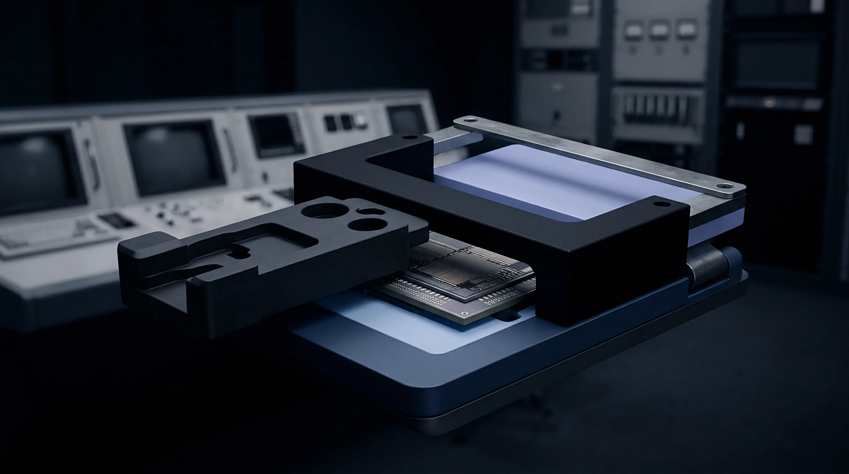
Profiling clock adjustments under simulated environmental ramps requires high-precision current analyzers and digital storage oscilloscopes. Test setups isolate the device inside a programmable chamber capable of ramping from minus 40 degrees Celsius to positive 85 degrees Celsius at up to 10 degrees Celsius per minute. A sub-GHz vector network analyzer or spectrum analyzer monitors transmission timing relative to an atomic rubidium reference standard, where oscillator noise sets baseline timing jitter.
Current profiling instruments capture microsecond-level spikes to verify that sensor acquisition cycles match modeled energy predictions. Meanwhile, logic analyzers monitor SPI and I2C lines to confirm hardware compensation registers receive updated load capacitance bytes within expected thermal intervals.
Compliance with IEEE 802.15.4g frame timing accuracy specifications voids module warranty coverage if clock drift exceeds maximum slot guard band allowances during thermal testing.

Systematic Test Execution and Qualification Failures
Verifying crystal compensation under rapid thermal transients requires rigorous bench monitoring. Common failure modes observed during laboratory thermal sweeps stem from software bugs, incorrect capacitive tuning parameters, or sensor lag:
- Thermal Sensor Hysteresis occurs when internal silicon sensors report lagged temperature values, delaying calibration updates during steep thermal ramps.
- Capacitance Trimming Saturation manifests when calculated offsets exceed the physical minimum or maximum of internal load capacitor arrays.
- Bus Contention Interruption happens when high-priority radio interrupts preempt I2C memory writes, dropping calibration updates.
- Fixed Point Arithmetic Overflow emerges in 32-bit math when polynomial equations exceed integer variable limits.
Specifying sub-GHz radio modules for harsh outdoor environments requires strict contractual boundaries in procurement specifications:
- Thermal Ramp Drift Limits mandate that real-time clock deviation remain below 20 parts per million across thermal gradients up to 5 degrees Celsius per minute.
- Guard Band Timing Budgets require sub-GHz mesh nodes to maintain alignment within a 200-microsecond window across all operational temperatures.
- Microampere Consumption Floor sets an absolute ceiling on average temperature sensor polling current draw during sleep states.
- Factory Calibration Dossier Delivery mandates that each silicon batch arrive with individual crystal turnover temperature parameters stored in flash memory.
Under Section 7.4 of the ETSI EN 300 220-1 sub-GHz wireless standard, hardware modules that fail to maintain frequency stability across specified environmental limits lose compliance certification for European commercial markets.

Trade

Crystal Oscillator Sourcing and Component Selection
Component selection balances initial bill-of-materials cost against firmware complexity and battery sizing. Standard 32.768 kHz tuning-fork crystals cost less than 0.15 US dollars in high-volume production, but using them demands dedicated software effort to write, test, and maintain thermal compensation algorithms. That software relies on internal microcontroller temperature sensors, which carry inherent tolerances of plus or minus 2 degrees Celsius to plus or minus 5 degrees Celsius unless individually calibrated at the factory.
High-precision standalone Temperature Compensated Crystal Oscillators integrate an internal temperature sensor and analog compensation ASIC directly into the crystal package. A standalone TCXO holds frequency stability within plus or minus 2 parts per million across the full minus 40 degrees Celsius to positive 85 degrees Celsius industrial temperature range. Bypassing software compensation simplifies firmware architecture and guarantees deterministic slot timing without microcontroller intervention, though it adds to the hardware bill of materials.

Commercial Impact of TCXO Modules versus Software Compensated Tuning Forks
A standalone TCXO adds between 0.85 US dollars and 1.80 US dollars to the module bill of materials. In a smart lighting or metering deployment of 500,000 nodes, that hardware choice increases total procurement costs by up to 900,000 US dollars. Opting for low-cost tuning-fork crystals instead avoids that component cost, though factory calibration sweeps during board-level testing add roughly 0.12 US dollars per unit in manufacturing test time.
Battery sizing introduces secondary financial tradeoffs. Dynamic software compensation allows mesh nodes to keep radio guard bands tight, cutting active receiver listening time. That lower duty cycle often permits smaller primary lithium thionyl chloride cells ~ moving from 2/3 AA to 1/2 AA, for instance.
A battery savings of 0.45 US dollars per unit helps offset software development overhead over multi-year deployments. Sourcing teams weigh total landed cost by combining component costs, factory test time, battery chemistry, and long-term maintenance risks before finalizing hardware production specifications.