Meaning
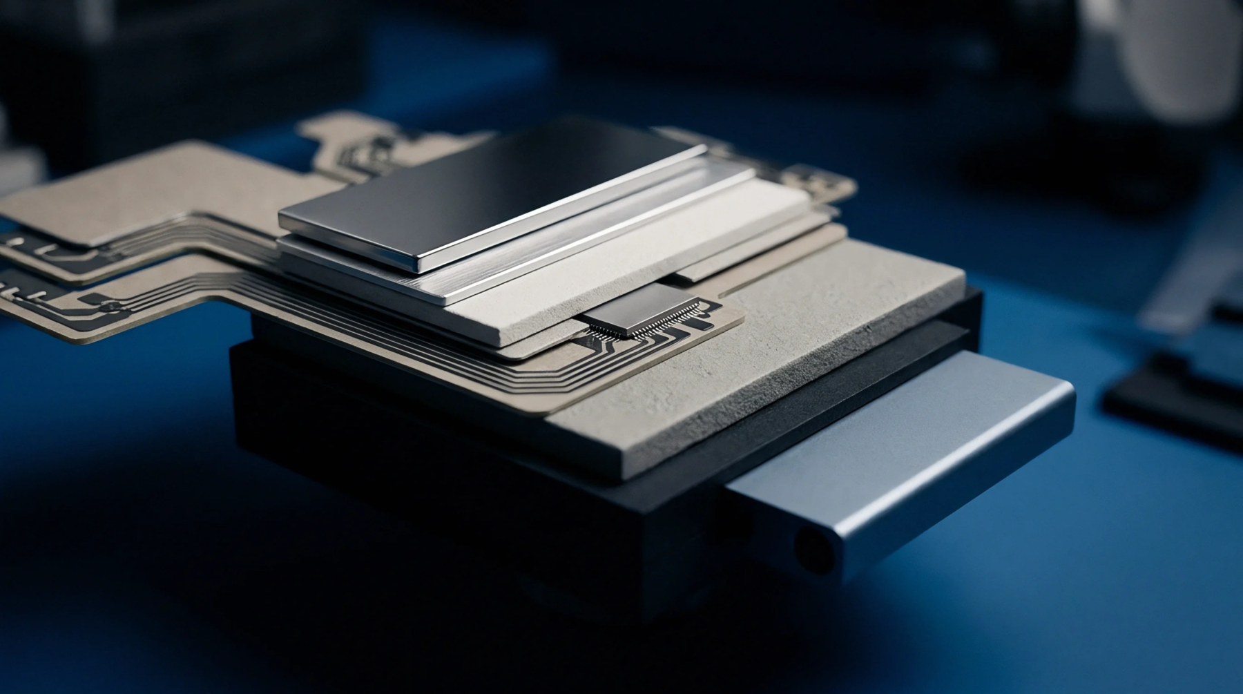
Metallic covers soldered onto printed circuit boards isolate sensitive radio components from electromagnetic interference. Utilizing a faraday shielding can prevents emissions from on-board processors and power converters from disrupting the receiver circuitry. This physical barrier blocks both incoming and outgoing electromagnetic fields, ensuring compliance with global emission standards.
It represents the primary defense against board-level noise coupling in compact multi-radio devices.
Board Layout
Printed circuit board design relies on metal enclosures to partition noisy digital blocks from sensitive RF receivers. When integrating a faraday shielding can, engineers must leave sufficient clearance for automated solder paste inspection and pick-and-place machines. The shield attaches directly to the ground plane through multiple solder points to create a continuous electrical cage.
This layout choice minimizes high-frequency loop areas that act as parasitic antennas.
Thermal Management
Enclosed metal shields trap heat generated by power amplifiers and processors, risking thermal runaway if unmanaged. Designers solve this by using perforated metal or thermal interface materials that connect the hot components directly to the shield top. This design channel distributes thermal energy across a wider board surface area.
Testing Protocol
Factory verification procedures require testing the RF performance both before and after the shield is permanently attached. Removable shield lids allow technicians to probe internal test points during debugging. This flexibility prevents the costly scrapping of complete boards due to simple component failures.