Conductive Enclosure Shielding Effectiveness and Radiated Harmonic Leakage Dynamics
Enclosure seams and apertures control radiated harmonic leakage through transfer impedance, dictating gasket specs needed for global radio grants.

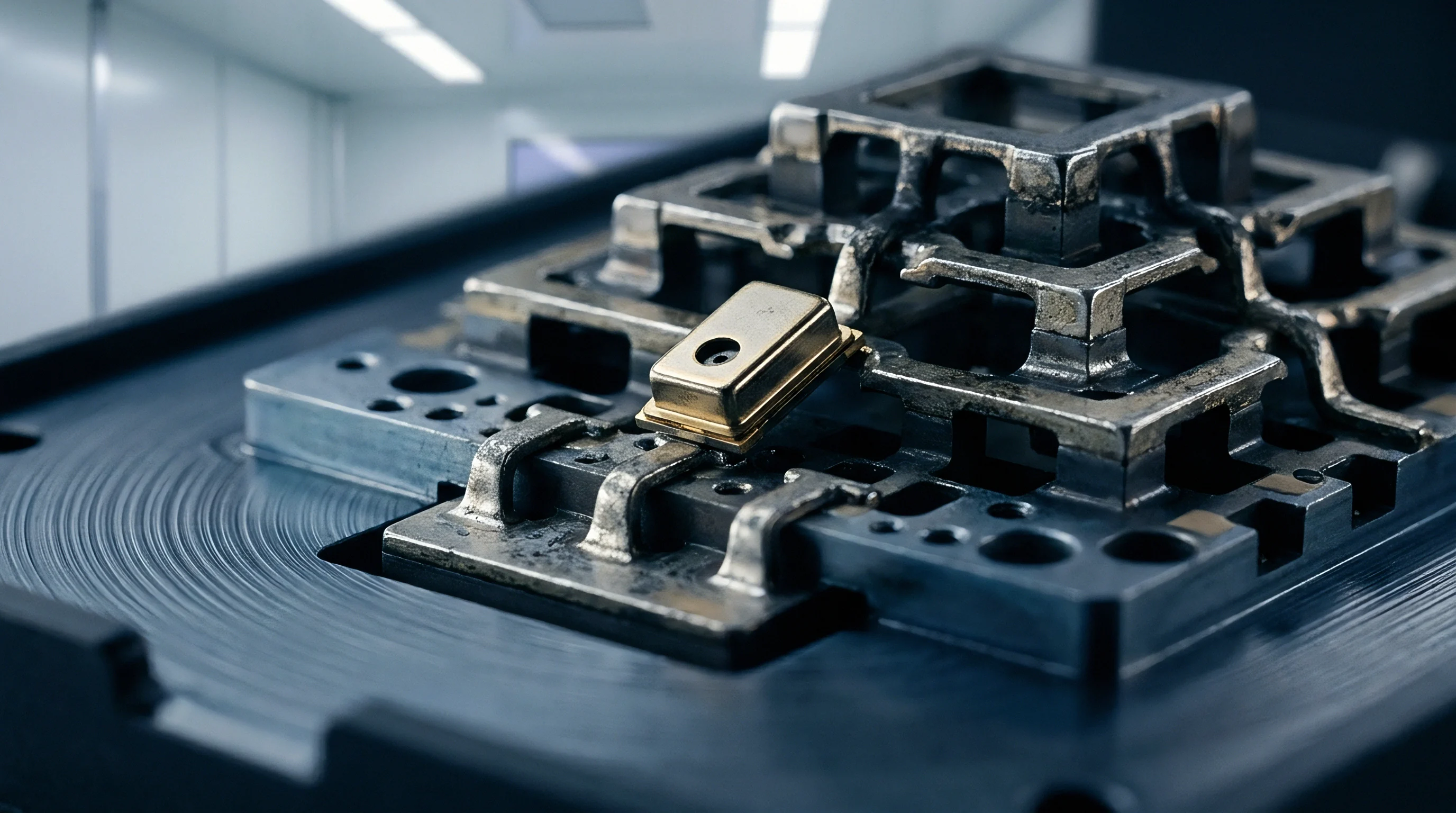
Aperture
Metal housings around high-frequency radio transmitters serve as the primary physical barrier against unwanted electromagnetic fields. A solid box of high-conductivity metal like aluminum or copper theoretically offers near-infinite shielding effectiveness, but real-world enclosures require functional openings. Display cutouts, heat dissipation vents, seam joints, input-output ports, and assembly splits interrupt the continuous conductive wall.
When internal fields interact with these structural discontinuities, the openings act as aperture antennas. At fundamental operating frequencies, an enclosure aperture might measure a small fraction of the carrier wavelength and leak very little signal. But when power amplifiers run near saturation, non-linear distortion produces high-order harmonics that stretch into the multi-gigahertz regime.
As frequency rises and wavelength shrinks, physical openings that seemed electrically negligible at fundamental frequencies approach sub-quarter-wavelength or half-wavelength dimensions. At these harmonic wavelengths, the cutouts turn internal wall currents into high-efficiency slot radiators, creating localized harmonic leakage that can easily disrupt compliance with international radio standards.
Shielding effectiveness measures the ratio of field strength at a point prior to installing a shield to the field strength at that same point after positioning the shield. Expressed in decibels, total shielding effectiveness incorporates three distinct mechanisms: reflection loss, absorption loss, and internal multi-reflection re-transmission correction. Schelkunoff’s classic formulation describes this behavior:
SE = R + A + B
Reflection loss depends primarily on the impedance mismatch between the incident wave and the intrinsic impedance of the enclosure wall material. Absorption loss measures energy converted to heat as the wave travels through the conductive sheet, governed by skin depth. Skin depth represents the distance over which field amplitude drops to 1/e of its initial value based on material permeability, conductivity, and signal frequency.
Higher harmonic frequencies shrink the skin depth, which dramatically increases absorption loss through solid metal. A two-millimeter aluminum wall, for instance, provides over two hundred decibels of absorption loss at five gigahertz. Solid metal walls almost never fail shielding audits from bulk penetration; degradation happens almost exclusively at physical apertures where internal boundary currents hit mechanical obstacles and re-radiate into external space.

Electromagnetic Field Attenuation in Enclosure Cavities
Radio frequency energy from internal power amplifiers rebounds within metallic structures, creating standing wave patterns at discrete locations. Enclosures act as resonant cavities defined by specific boundary conditions. When internal dimensions equal integer multiples of half-wavelengths, field strength peaks sharply at those resonant frequencies.
These cavity modes convert moderate internal harmonic emissions into extreme electric and magnetic field concentrations along interior housing walls.
If an aperture sits at an internal field maximum, coupling efficiency spikes. Electric field coupling occurs when internal voltage gradients span across an opening. Magnetic field coupling occurs when surface currents flow perpendicular to an aperture slot length.
When surface currents encounter an open slot, current vectors cannot bridge the physical gap. The boundary current splits, circulating around the ends of the slot to complete its return path. This diverted current flow produces an alternating magnetic dipole moment across the aperture.
The magnetic dipole moment excites an external field, converting internal circuit noise directly into radiated harmonic energy.
The field intensity radiated by an aperture depends on its maximum linear dimension rather than its total cross-sectional area. A wide rectangular mesh composed of tiny square holes restricts surface current loop circumferences, maintaining relatively high field attenuation. A single narrow slit with the exact same total surface area permits long current detours, yielding severe radiated harmonic leakage.
When evaluating enclosure performance across high harmonics, engineers calculate the aperture cutoff frequency. Above the cutoff frequency, the aperture acts as a high-pass waveguide, propagating energy directly outside the enclosure without structural attenuation.
| Aperture Max Dimension (mm) | Cutoff Frequency (GHz) | Fundamental Attenuation at 2.4 GHz (dB) | 2nd Harmonic Attenuation at 4.8 GHz (dB) | 3rd Harmonic Attenuation at 7.2 GHz (dB) | 5th Harmonic Attenuation at 12.0 GHz (dB) |
|---|---|---|---|---|---|
| 50.0 | 3.00 | 14.2 | -3.1 | -8.4 | -14.2 |
| 25.0 | 6.00 | 22.5 | 10.8 | -2.5 | -9.1 |
| 12.5 | 12.00 | 31.1 | 19.4 | 11.2 | -0.8 |
| 6.0 | 25.00 | 39.8 | 28.5 | 20.3 | 10.5 |
| 2.0 | 75.00 | 52.4 | 41.2 | 33.0 | 23.2 |
Data in the table illustrates how aperture length bounds high-frequency suppression. Negative attenuation values reflect resonance enhancement, where internal cavity field amplification combined with aperture coupling yields higher external radiated emissions than if the shield were entirely absent. Small cutouts that easily pass certification at two point four gigahertz frequently suffer total attenuation collapse when tested against fifth-order harmonics at twelve gigahertz.
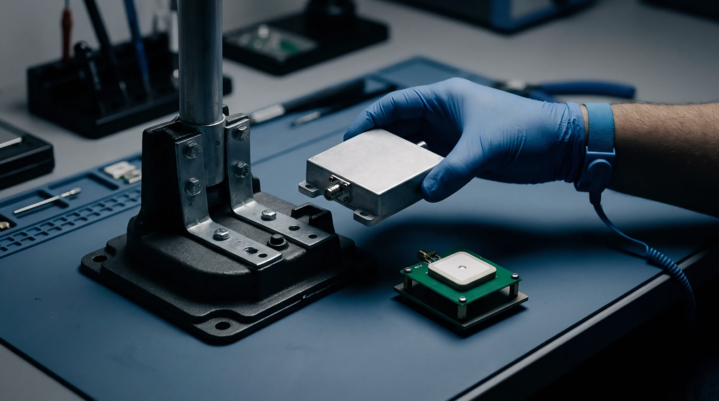
Slot Radiator Mechanics and Dipole Equivalence
Unintentional openings cut into thin conductive walls transform structural penetrations into efficient magnetic dipoles when internal surface currents intersect them. Applying Babinet’s principle establishes a direct electromagnetic duality between a metallic dipole antenna and a slot aperture cut into an infinite conductive plane. The electric field pattern of a thin slot matches the magnetic field pattern of a complementary wire dipole, while the slot magnetic field pattern mirrors the dipole electric field pattern.
The radiation resistance of a narrow half-wavelength slot cut in a thin sheet equals approximately 365 ohms, presenting a highly efficient impedance match to free space.
When the fundamental output of an internal transmitter operates at two point four gigahertz, its half-wavelength equals sixty-two point five millimeters. A housing seam split of sixty-two point five millimeters radiates fundamental carrier power with near-unity coupling efficiency if unshielded. If the internal power amplifier exhibits non-linear harmonic distortion, significant energy exists at seven point two gigahertz (third harmonic, half-wavelength of twenty-two point eight millimeters) and twelve gigahertz (fifth harmonic, half-wavelength of twelve point five millimeters).
A localized mechanical flex or loose bolt spacing that creates a twelve point five millimeter slot gap will remain benign during fundamental emission scans but will act as a resonant half-wavelength slot radiator at twelve gigahertz. Peak gain from such slot apertures reaches two point one five dBi, turning internal noise into intense directional radiation spikes during compliance scans.
A 10-millimeter slot aperture reduces enclosure attenuation by 18 decibels at the fifth harmonic frequency of 12 gigahertz compared to its fundamental performance.
Quantifying aperture radiation involves evaluating the surface current density vector, J_s, approaching the slot boundary. The magnitude of radiated power scales with the square of the slot length and the square of the normal component of surface current interrupted by the slot. When designing chassis cooling arrays, replacing long rectangular slots with arrays of circular perforated holes preserves airflow while dramatically truncating current detour paths.
A circular hole of diameter D exhibits an aperture transfer polarizability proportional to D cubed. Splitting a single large opening into a array of smaller holes restricts magnetic dipole moments, suppressing radiated harmonic emissions by twenty to forty decibels in the upper microwave bands.

Harmonic Field Penetration at High Frequencies
Nonlinear distortion generated inside power stage transistors generates spectral components at integer multiples of the fundamental operating channel. Solid-state switches, digital clock trees, power management converters, and power amplifier saturation drive harmonic current spikes along printed circuit board ground traces. These high-frequency ground currents conduct directly into the interior metal surfaces of the enclosure via standoff screws, ground springs, and connector shells.
Once injected into the enclosure chassis, these harmonic surface currents propagate across interior walls, seeking low-impedance paths back to the RF source.
Harmonic current field penetration through enclosure apertures exhibits severe frequency dependency. Below the aperture cutoff frequency, field amplitude decays exponentially with distance along the depth of the opening. This decay mechanism forms the basis of waveguide-below-cutoff design.
The attenuation constant alpha for a rectangular waveguide below cutoff operating well below its fundamental cutoff frequency is calculated as:
alpha = (2 pi / lambda_c) sqrt(1 – (f / f_c)^2)
Where lambda_c represents the cutoff wavelength and f_c represents the cutoff frequency. Increasing wall thickness converts a simple aperture into a waveguide-below-cutoff channel, forcing exponential spatial decay of internal fields. If the wall thickness matches or exceeds the slot length, low-frequency attenuation stays high.
However, as harmonic emissions approach f_c, the term under the square root approaches zero, causing the attenuation constant to collapse. At frequencies above f_c, electromagnetic energy propagates through the aperture with zero theoretical spatial attenuation, governed only by entry and exit reflection losses.
Failure modes in conductive enclosure shielding emerge from complex interactions between aperture geometry, internal cavity resonances, and harmonic source locations:
- Resonant Slot Excitation occurs when an enclosure gap length equals integer multiples of half the harmonic wavelength, matching free-space radiation impedance.
- Cavity-Aperture Coupling Alignment takes place when internal standing wave voltage nodes align directly with physical housing cutouts, accelerating field transmission.
- Connector Shell Shield Breaches emerge when peripheral input-output connectors lack three-hundred-sixty-degree conductive grounding to the chassis panel, leaking high-frequency ground current harmonics directly onto external cable shields.
- Display Bezel Boundary Leakage manifests along non-conductive glass-to-metal adhesive joints where conductive gaskets are omitted to preserve visual margins.
- Internal Cable Harness Radiation happens when unshielded ribbon cables carrying harmonic-rich digital clock signals run parallel to enclosure seam gaps, magnetically coupling high-frequency energy out of the box.
Understanding these failure mechanisms allows engineering teams to identify vulnerabilities early in product development cycles. Field distributions inside small metallic enclosures remain highly non-uniform. A millimeter shift in printed circuit board placement within an enclosure can move a power amplifier output trace away from a cavity electric field maximum, reducing radiated harmonic leakage by fifteen decibels without changing the chassis metal tooling.
Operating margins drop rapidly under these subtle mechanical conditions.
Anechoic chamber scans consistently confirm this sensitivity.
What remains unresolved in aperture theory is predicting the exact coupling coefficient between internal non-linear source impedances and complex multi-hole enclosures when structural tolerances alter aperture geometry under mechanical stress during field deployment.


Seam
Joining two metallic housing shells creates a mechanical interface where electrical continuity dictates overall field confinement performance. Physical enclosure seams interrupt current pathways across chassis panels. Unless mating surfaces maintain low-resistance contact around the entire perimeter, the joint forms a distributed slot array.
Seam performance depends on micro-scale mechanical contact, surface oxidation, fastener clamping pressure, and structural flange stiffness. At fundamental frequencies, wider bolt spacing may maintain adequate electrical continuity to pass coarse emission standards. At higher harmonic frequencies, micro-gaps between fastener points turn into phase-shifted array radiators that convert a tight mechanical assembly into a major source of radiated harmonic emissions.
Quantifying joint electrical continuity requires evaluating transfer impedance. Transfer impedance, Z_T, relates the open-circuit voltage induced on the exterior side of a seam to the total surface current flowing along the interior side of the joint per unit length. Expressed in ohms-meters or milliohms-meters, transfer impedance serves as the core metric for evaluating seam shielding quality:
Z_T = (1 / I_int) (dV_ext / dz)
Low transfer impedance indicates an effective electrical joint that prevents internal chassis currents from developing external potential differences. High transfer impedance signifies significant electromagnetic leakage. Transfer impedance incorporates two primary components: a resistive component derived from direct contact resistance across microscopic surface asperities, and an inductive component originating from magnetic flux linkage through gaps between contact points.
As harmonic frequencies escalate into the gigahertz regime, the inductive term omega times M_T dominates the transfer impedance, causing joint leakage to rise linearly with frequency.

Transfer Impedance across Conductive Joint Interfaces
Currents flowing along the interior metallic skin cross mechanical boundaries, inducing open-circuit potential differences on external conductive surfaces. Mechanical contact between two metal surfaces never occurs across the total nominal flange area. Microscopic surface roughness limits actual metal-to-metal contact to isolated peaks known as asperities.
Under standard assembly torques, true contact area is often less than one percent of the apparent flange surface.
Electric current lines converge tightly to pass through these microscopic contact asperities, creating constriction resistance. Constriction resistance combines with thin-film oxide resistance to establish the baseline direct-current resistance of the seam. When high-frequency harmonic currents flow across the joint, the restricted contact points force surface currents to detour around non-contact regions.
These localized current loops generate magnetic flux that leaks across the seam boundary, establishing a mutual inductance M_T across the joint.
Measuring transfer impedance across high harmonic frequencies reveals distinct performance regimes. At frequencies below ten megahertz, transfer impedance remains constant, bounded by direct-current contact resistance. Between ten megahertz and one gigahertz, transfer impedance increases at twenty decibels per decade due to mutual inductance flux leakage.
Above one gigahertz, internal structural dimensions match the spatial wavelength of harmonic signals, causing phase shifts across the seam length. The seam transitions from a localized lump impedance into a distributed transmission line, generating complex spatial radiation patterns.

Fastener Spacing and Dynamic Contact Resistance
Clamping bolts apply localized compressive force, causing elastic deflection along conductive flanges between individual retention points. When fasteners tighten, high compressive stress develops immediately adjacent to the bolt heads. Moving away from the fastener locations along the flange, mechanical compression decays exponentially.
If the spacing between fasteners exceeds structural deflection limits, the metal flanges bow outward slightly, creating microscopic gaps mid-way between bolt locations.
Flange deflection creates periodic contact pressure distribution along the seam perimeter. Where compression pressure drops below critical thresholds, metallic contact asperities separate, breaking direct electrical continuity. These periodic non-contact zones form slot apertures whose physical length equals the inter-fastener pitch minus the effective bolt head contact diameter.
At high harmonic frequencies, if the inter-fastener pitch approaches half a wavelength, intense local resonance occurs along the seam.
Evaluating joint behavior requires precise measurement protocols. Mapping transfer impedance and contact resistance across physical seams relies on a structured validation procedure:
- Clean mating metal flanges using isopropyl alcohol to eliminate oil residues, surface dust, and processing contaminants without damaging underlying metal finishes.
- Mount the chassis assembly into a specialized triaxial transfer impedance test fixture capable of driving controlled surface currents up to eighteen gigahertz.
- Apply calibrated mechanical torque to all enclosure fasteners using a digital torque wrench, recording compression increments from zero point two Newton-meters up to one point eight Newton-meters in zero point two Newton-meter steps.
- Inject high-frequency sweeping signals from a calibrated vector network analyzer across the internal chassis boundary, measuring external coupled voltage via a matched fifty-ohm sensing line.
- Calculate transfer impedance per meter across discrete harmonic frequency points, logging values at fundamental, second, third, fifth, and seventh harmonic frequencies.
- Subject the clamped enclosure to thermal cycling from minus forty degrees Celsius to plus eighty-five degrees Celsius inside an environmental chamber for one hundred cycles while monitoring continuous joint contact impedance.
Fasteners and mechanical fittings loosen over operational lifetimes.
Gasket materials gradually deform under sustained compression.
Microscopic gaps then begin leaking high-harmonic RF energy.
Thermal expansion mismatches accelerate seam degradation. Aluminum exhibits a coefficient of thermal expansion of twenty-three times ten to the minus sixth per degree Celsius, whereas stainless steel fasteners exhibit sixteen times ten to the minus sixth per degree Celsius. Thermal cycling causes differential expansion across the seam interface, generating microscopic scrubbing actions across contact asperities.
Over time, this mechanical scrubbing breaks surface metal bonds, inducing micro-fretting wear that increases joint contact resistance by several orders of magnitude.

Surface Oxidation and Galvano-Chemical Degradation
Environmental exposure introduces humidity and atmospheric pollutants into mating structural flanges, accelerating microscopic chemical transformations. Bare aluminum rapidly forms a self-passivating aluminum oxide coating when exposed to air. While aluminum oxide protects the structural integrity of the metal, it acts as an electrical insulator with a dielectric constant near nine.
As insulating oxide films grow across mating flanges, direct metallic contact asperities convert into capacitive junctions, drastically altering high-frequency current transfer dynamics.
Galvanic corrosion occurs when dissimilar metals contact each other in the presence of an electrolyte, such as ambient moisture containing dissolved salt or industrial pollutants. Standard corrosion potential tables establish strict limits for compatible metal pairings. When the galvanic potential difference between mating chassis components exceeds zero point fifteen volts for harsh environments or zero point twenty-five volts for controlled indoor environments, localized electrochemical reactions degrade conductive contact surfaces.
| Gasket Material Class | Initial Joint Resistance (mΩ·cm) | Transfer Impedance at 1 GHz (mΩ/m) | Transfer Impedance at 10 GHz (mΩ/m) | 1000-Hour Salt Spray Impedance Growth (%) | Radiated Leakage Delta at 5th Harmonic (dB) |
|---|---|---|---|---|---|
| Nickel-Graphite Filled Silicone | 12.4 | 1.8 | 45.2 | +18.5% | Baseline |
| Silver-Plated Aluminum Elastomer | 2.1 | 0.3 | 12.8 | +342.0% | -11.4 |
| Beryllium Copper Fingerstock | 0.8 | 0.1 | 8.4 | +45.0% | -15.1 |
| Oriented Wire in Silicone | 8.5 | 1.2 | 28.6 | +32.0% | -4.2 |
| Conductive Form-in-Place Foam | 35.0 | 5.4 | 112.0 | +85.0% | +7.8 |
Data from salt-spray testing demonstrates the complex balance between initial electrical performance and long-term environmental durability. Silver-plated aluminum elastomers offer exceptionally low initial transfer impedance, yielding superior suppression of high-harmonic leakage during initial bench testing. However, when exposed to marine or industrial environments, severe galvanic activity between silver particle fillers and aluminum substrate flanges causes aggressive oxide growth, driving a three-hundred-forty-two percent increase in transfer impedance.
Nickel-graphite filled silicone presents higher initial transfer impedance but maintains remarkable environmental stability, resisting galvanic decay under prolonged humidity exposure.
Fastener torque relaxation causes seam transfer impedance to double within five hundred thermal cycles in aluminum enclosures.
High-frequency surface currents flow directly along enclosure seams.
Electrical resistance across gasket interfaces rises as surface oxidation develops.
During factory gate audits, mechanical assembly drawings often specify standard manufacturing tolerances without explicitly listing high-frequency electrical seam continuity as an inspectable quality criterion on purchase order documentation.


Mitigation
Engineers suppress unwanted harmonic field propagation using physical hardware modifications applied directly to housing mating surfaces and internal cavities. Mitigating high-frequency harmonic leakage demands systematic control of aperture dimensions, joint transfer impedance, structural stiffness, and internal cavity Q-factors. Relying solely on raw metal-to-metal contact rarely guarantees compliance across extended product lifetimes due to manufacturing variations, thermal stress, and environmental oxidation.
Incorporating specialized conductive gaskets, localized shielding cans, and magnetic microwave absorbers eliminates harmonic leakage paths before radiated energy breaks outside product enclosures.
Conductive gaskets fill structural gaps caused by mechanical tolerances and flange deflection. When compressed between enclosure mating surfaces, the gasket deforms elastically, forcing conductive particles or spring elements into continuous physical contact with both sides of the joint interface. Selecting an appropriate gasket requires evaluating mechanical compression set, surface contact resistance, galvano-chemical compatibility, RF transfer impedance, and high-frequency attenuation performance.

Conductive Gasket Compression and Contact Physics
Elastomer cores filled with nickel-coated graphite particles provide continuous resilient bridging across mechanical enclosure gaps. Gasket compression dynamics follow a non-linear load-deflection curve. Under-compression results in inadequate contact pressure, leaving microscopic gaps that permit high-harmonic field leakage.
Over-compression damages the internal elastomer matrix, fracturing particle-to-particle conductive chains and permanently compromising elastic recovery performance.
Optimal gasket deflection typically spans twenty to fifty percent of total uncompressed gasket height. Within this nominal deflection window, conductive elastomer gaskets deliver extremely low contact resistance while maintaining adequate spring force to accommodate dynamic flange flexing. For high-frequency harmonic mitigation, gasket selection shifts toward materials featuring fine particle distributions or continuous spring contact geometry, such as beryllium copper fingerstock or knitted wire mesh over silicone cores.
Beryllium copper fingerstock provides high mechanical deflection ranges with low closing forces and superior wear resistance, rendering it ideal for frequently opened access doors or high-cycle enclosure covers.
Selection of harmonic suppression components follows strict engineering trade-offs between mechanical compliance, electrical impedance, environmental sealing, and landed cost:
- Conductive Elastomers offer integrated IP67 environmental fluid sealing combined with effective RF shielding up to ten gigahertz, requiring high clamping force and rigid flange designs.
- Beryllium Copper Fingerstock provides the lowest transfer impedance across microwave bands up to forty gigahertz, providing minimal compression force requirements but zero environmental fluid sealing.
- Form-in-Place Gaskets enable automated robotic dispensing directly onto complex enclosure paths, reducing labor costs while providing moderate high-frequency shielding performance up to six gigahertz.
- Oriented Wire in Silicone embeds solid monel or aluminum wires perpendicular to flange surfaces, providing outstanding point-contact penetration through non-conductive surface oxides under high bolt pressures.
- Conductive Fabric-Over-Foam delivers exceptionally soft closing force requirements for plastic housings plated with conductive coatings, but suffers from severe mechanical wear under high-friction sliding conditions.
Integrating gaskets into housing design demands precise mechanical pocket geometry. Gasket grooves must provide sufficient volume to accommodate material displacement under compression, preventing gasket extrusion into internal cavity spaces. Furthermore, non-conductive surface treatments such as anodization, paint, or powder coatings must be masked off completely along gasket contact tracks to maintain metallic conductivity.

Can Shielding Can Design Prevent Harmonic Leakage?
Board-level metal covers fitted over RF front-end circuitry establish localized Faraday cages before unwanted electromagnetic noise reaches outer product boundaries. Shielding cans encapsulate power amplifiers, synthesizers, and switching regulators directly at the printed circuit board level. Isolating non-linear RF sources beneath board-level cans isolates high-amplitude harmonic fields from the main enclosure cavity, drastically relaxing chassis seam transfer impedance requirements.
Designing effective board-level shielding cans requires continuous perimeter grounding. SMT shielding frames soldered directly to ground planes on printed circuit boards establish seamless conductive perimeters. Removable metal covers snap into SMT frames, providing mechanical access for component rework while maintaining multi-point spring contact along frame walls.
However, pickup pin holes, structural dimples, and cover snap-latch cutouts introduce small aperture arrays into the shielding can structure. At fifth-order harmonic frequencies above ten gigahertz, these tiny cover apertures can radiate significant energy into the interior enclosure volume if hole dimensions are not tightly constrained.
Shifting phase alignment alters the overall beam shape.
Absorptive materials reduce internal standing waves.
High-order harmonics readily escape through narrow structural slots.
Internal cavity damping complements structural shielding. When internal enclosure dimensions excite cavity resonances, microwave absorbers convert standing electromagnetic wave energy into heat, lowering cavity quality factors (Q-factors). Thin elastomer sheets filled with carbonyl iron powder or hexagonal ferrite flakes exhibit high magnetic loss tangents at microwave frequencies.
Positioning magnetic absorbers on internal enclosure walls near magnetic field intensity nodes dampens cavity resonances, suppressing field buildup by ten to twenty decibels across targeted harmonic bands.

Absorption Absorber Layering and Wave Suppression
Magnetic loss materials composed of iron silicide flakes suspended in silicone matrices convert high-frequency magnetic energy into thermal dissipation. Absorber effectiveness relies on magnetic permeability complex loss terms, mu double-prime, and electric permittivity complex loss terms, epsilon double-prime. At fundamental carrier frequencies around two point four gigahertz, high-grade absorbers maintain low magnetic loss, allowing desired RF signals inside traces to pass unattenuated.
At high harmonic frequencies between six gigahertz and eighteen gigahertz, magnetic loss parameters spike dramatically, absorbing stray fields before they reach enclosure seams.
Deploying microwave absorbers requires positioning material sheets directly over high-frequency surface current concentrations or lining internal housing caps above power amplifier modules. Reflective metal shielding reflects harmonic energy back toward internal circuit components, potentially inducing instability in sensitive front-end low noise amplifiers. Magnetic absorbers suppress fields via true energy dissipation rather than reflection, eliminating unwanted feedback loops inside enclosed housing volumes.
Evaluating harmonic mitigation performance requires establishing clear trade-off bounds between physical thickness, weight, mechanical closing force, and suppression bandwidth. The operational rule of thumb for effective harmonic control dictates that gasket fastener pitch must never exceed one-eighth of the wavelength of the highest harmonic frequency requiring regulatory suppression.


Compliance
Regulatory agencies evaluate radiated spurious emission scans across semi-anechoic environments before issuing market authorization. International radio equipment rules establish strict radiated emission ceilings across broad spectrum ranges, extending up to forty gigahertz for high-frequency transmitters. An enclosure that exhibits minor mechanical tolerance shifts or seam gaps can fail radiated harmonic emission checks, halting global shipment schedules.
Understanding standard limits, measurement methodologies, and grant permissive change rules allows engineering teams to maintain compliance while managing hardware modification budgets.
Under European Telecommunications Standards Institute rules, ETSI EN 300 328 governs wideband transmission systems operating in the two point four gigahertz ISM band. Clause 4.3.2.9 sets absolute radiated spurious emission limits. In the transmitter domain, spurious emissions outside operating bands must not exceed minus thirty-six dBm effective isotropically radiated power (EIRP) for frequencies between thirty megahertz and one gigahertz, and minus thirty dBm EIRP for frequencies between one gigahertz and twelve point seven five gigahertz.
In receiver standby modes, limits tighten to minus fifty-seven dBm EIRP below one gigahertz and minus forty-seven dBm EIRP above one gigahertz. Converting minus thirty dBm EIRP to field strength at a three-meter test distance yields approximately sixty-five point two dBuV/m, establishing a stringent threshold for radiated harmonic leakage.
In the United States, the Federal Communications Commission dictates radiated spurious limits under FCC Part 15 Subpart C (Section 15.247) for digital transmission devices and Subpart E (Section 15.407) for Unlicensed National Information Infrastructure devices. Section 15.209 establishes general field strength limits. For emissions falling into restricted frequency bands specified in Section 15.205, field intensity measured at three meters must not exceed five hundred microvolts per meter (fifty-four dBuV/m), equivalent to an EIRP of minus forty-one point two dBm.
Radiated harmonics falling inside restricted bands, such as the second harmonic of five gigahertz Wi-Fi transmitters falling into the restricted ten point six to twelve point seven gigahertz band, encounter this severe fifty-four dBuV/m average limit, leaving virtually zero margin for enclosure seam leakage.

Radiated Emission Test Plans for Enclosure Verification
Standardized measurement procedures place complete device assemblies on motorized turntables inside calibrated chambers to capture peak field intensity. Test configurations must reflect worst-case commercial operating modes. Devices under test execute specialized regulatory test software that forces continuous transmission at maximum rated power output across low, middle, and high operating channels.
The turntable rotates three hundred sixty degrees while a receiving antenna mounted on a motorized mast scans in height from one to four meters in both horizontal and vertical polarization states.
Below one gigahertz, radiated measurements take place inside Semi-Anechoic Chambers (SAC) equipped with conductive ground planes using biconical and log-periodic antennas. Above one gigahertz, testing transitions to Fully Anechoic Chambers (FAC) or SACs lined with floor absorbers, utilizing double-ridged guide horn antennas up to eighteen gigahertz and standard gain horn antennas up to forty gigahertz. The distance between the device under test and the receiving antenna is maintained at three meters or one meter depending on high-frequency noise floor limitations.
| Regulatory Jurisdiction | Standard Clause | Frequency Band (GHz) | Peak Field Strength Limit (dBμV/m at 3m) | Equivalent EIRP Threshold (dBm) | Chamber Measurement Uncertainty (dB) |
|---|---|---|---|---|---|
| United States (FCC) | Part 15.209 / 15.247 | 0.03 to 1.00 | 46.0 (Quasi-Peak) | -49.2 | ±4.1 |
| United States (FCC) | Part 15.205 (Restricted) | 1.00 to 40.00 | 74.0 (Peak) / 54.0 (Avg) | -21.2 (Peak) / -41.2 (Avg) | ±5.2 |
| European Union (ETSI) | EN 300 328 / Clause 4.3.2.9 | 1.00 to 12.75 | 65.2 (Peak) | -30.0 | ±4.8 |
| Japan (MIC / Giteki) | Ordinance Reg. Article 2-1-19 | 1.00 to 26.00 | 54.0 (Average) | -41.2 | ±5.0 |
| China (SRRC) | Radio Regulation Notice 2021-129 | 1.00 to 12.75 | 65.2 (Peak) | -30.0 | ±5.2 |
Chamber measurement uncertainty introduces commercial risk during final approval scans. CISPR 16-4-2 specifies standard chamber uncertainty budgets ranging from four to five point two decibels for high-frequency radiated emissions. If a device under test exhibits radiated harmonic leakage measuring minus thirty-two dBm EIRP against a minus thirty dBm regulatory threshold, laboratory quality policies may classify the result as an ambiguous pass or a conditional fail due to measurement uncertainty overlapping the regulatory limit line.

Permissive Change Boundaries for Housing Structural Modifications
Filing updates with certification bodies becomes mandatory whenever physical chassis changes alter the previously documented radiated RF field spectrum. Integrating a pre-certified modular radio into a finished host product relies on modular grant conditions. Modular approvals allow host integrators to reference the module’s existing FCC ID or ISED certificate, provided antenna gains and physical host integration rules are strictly maintained.
However, introducing metal enclosure modifications, adding conductive gaskets, or altering internal PCB mounting standoffs after initial grant approval triggers regulatory permissive change rules.
Under FCC rules, hardware modifications fall under Class I or Class II Permissive Changes (C2PC):
- Class I Permissive Changes encompass minor structural or enclosure changes that do not degrade radiated spurious emissions or alter fundamental radio characteristics, requiring internal documentation retaining test data without mandatory FCC filing submission.
- Class II Permissive Changes apply when enclosure modifications alter radiated spurious emission profiles or introduce new metallic surroundings that degrade harmonic attenuation, requiring formal test report submission to a Telecommunications Certification Body (TCB) and updated public grant filings.
- Modifications Triggering New Grants include structural changes that alter fundamental antenna trace layouts, increase RF output power settings, or change radio operational protocols, forcing a complete new equipment authorization application under a unique FCC identifier.
ETSI EN 300 328 clause 4.3.2.9 reclassifies any radiated harmonic emission above minus thirty decibels milliwatts as an immediate type-approval rejection.
Managing permissive change risks requires maintaining rigorous baseline test records. If a host manufacturer modifies an aluminum enclosure by adding decorative ventilation slots, they must perform pre-compliance chamber scans. If high-harmonic emissions increase by more than three decibels compared to the original modular grant baseline, a Class II Permissive Change filing becomes mandatory before commercial units ship to market.
Commercial Qualification Deadlines and Testing Retest Expenses
Unplanned laboratory failures during final spurious emission scans create severe scheduling bottlenecks across global launch windows. Booking accredited compliance chamber time costs between two thousand and three thousand five hundred dollars per eight-hour shift. When a product fails radiated harmonic limits at twelve gigahertz due to seam leakage, the commercial impact extends far beyond immediate chamber fees.
A typical retest cycle involves root-cause physical diagnosis, mechanical gasket re-engineering, sample retrofitting, and chamber re-booking lead times. Retesting delays market entry by four to eight weeks. For example, a late-stage enclosure seam rework delayed one European commercial hardware launch by six weeks, absorbing forty-two thousand dollars in combined chamber fees, expedited tooling charges, and agent re-filing expenses.
Regulatory grant limits remain strictly enforceable.
Official test reports document every compliance boundary.
Final regulatory verification demands explicit physical proof.
To avoid compliance failures, engineering practices implement strict procurement contract clauses with housing suppliers and contract manufacturers. A standard purchasing contract clause specifies: The supplier warrants that all conductive housing components and conductive gaskets supplied under this agreement shall conform to mechanical drawing tolerances and maintain a seam transfer impedance of less than two milliohms-meters across the frequency band from thirty megahertz to eighteen gigahertz, and any lot delivering radiated harmonic emissions exceeding target compliance limits due to material or dimensional non-conformance shall be returned for immediate credit at supplier expense.