Establishing Mechanical Loss Thresholds and Tooling Wear Allocation in Fiber Reinforced Injection Molding
Erosion at injection gates breaks glass fibers and degrades tensile properties, requiring empirical wear thresholds and contractual refurb reserves.


Erosion
High-velocity thermoplastic melt carrying short glass fibers creates severe abrasive shear stress along cavity walls. The abrasive mechanical action concentrates heavily wherever flow streamlines change direction, such as runner turns, core pins, and gate entrances. Solid glass filaments act as micro-cutting edges against the metal matrix of the mold.
The rate of metal removal scales non-linearly with fiber loading, flow velocity, and melt viscosity. When processing 30 percent glass fiber reinforced polyamide 66, localized wear rates at restricted gates exceed those of unreinforced resins by two orders of magnitude.

Tribological Mechanisms in High Velocity Fiber Flow
Polymer matrices carrying rigid reinforcing elements generate localized micro-plowing along molten flow paths. As glass or carbon fibers travel through channels, hydrodynamic lift forces align them parallel to flow, but high wall shear stress forces hard filament tips into direct contact with the steel substrate. Matrix resins transfer applied forces directly to these contact points.
Micro-scratching strips away native metal oxide passivation layers, exposing fresh steel to chemical oxidation from resin off-gassing and elevated temperatures. Glass fibers act as abrasives. This synergistic wear process continuously strips thin layers of steel from runner walls and cavity features.
Wear severity depends on the hardness differential between the abrasive fiber and the mold steel. E-glass fibers exhibit a Mohs hardness of 6.5, corresponding to approximately 800 Vickers Hardness (HV). Standard H13 tool steel hardened to 52 HRC possesses a hardness of approximately 540 HV.
Hardened steel resists high friction. Because the abrasive phase remains harder than the tool steel substrate, physical gouging and material removal occur during every injection stroke. Carbon fiber reinforced compounds exhibit lower volumetric wear rates due to the self-lubricating graphite structure of carbon, though high shear rates still induce notable erosion on unprotected steel lands.
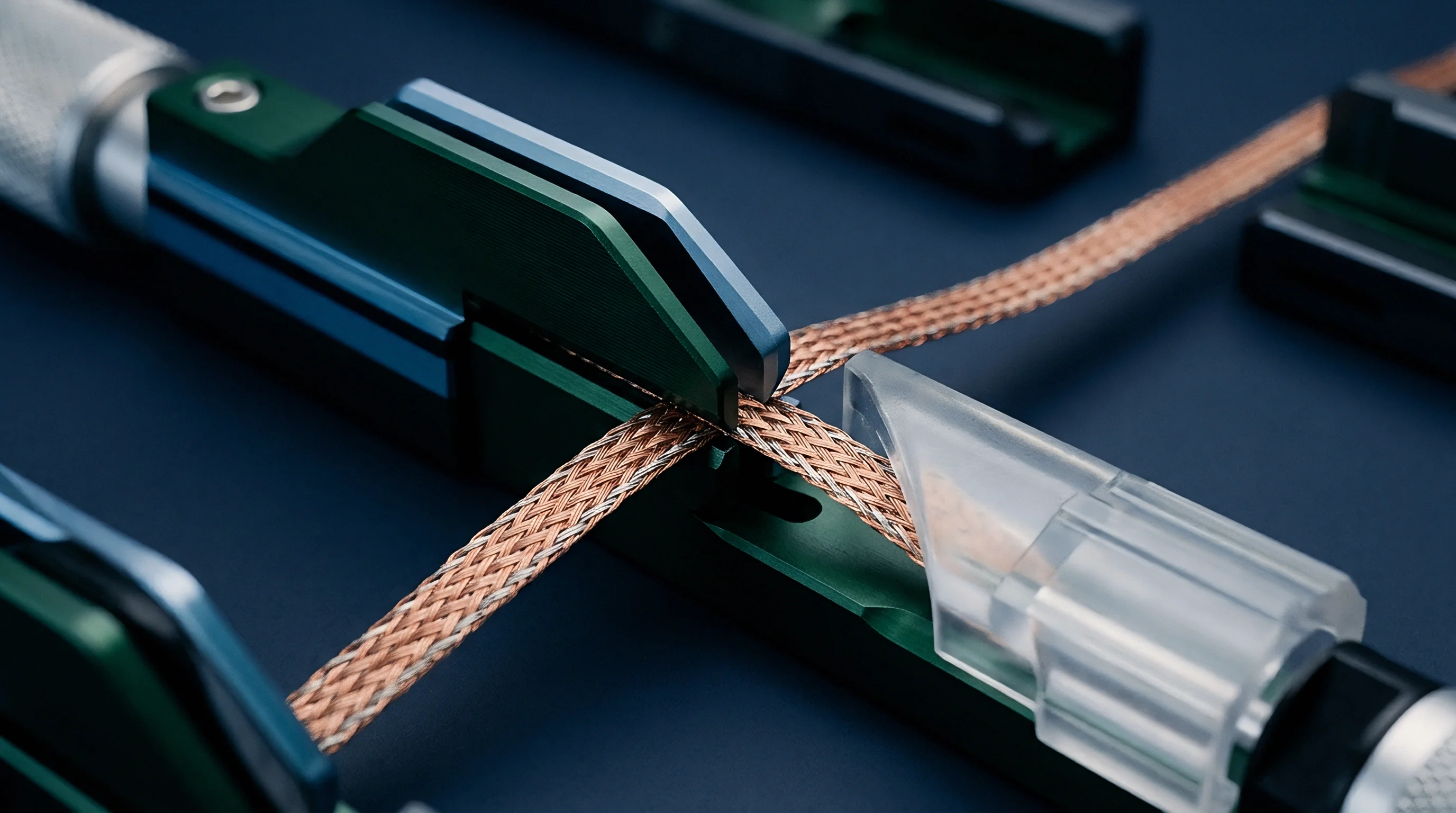
Mold Tool Surface Microstructure and Cavity Degradation
Repeated contact between exposed mineral reinforcement and steel substrates converts smooth machining marks into deep parallel scoring tracks. Initial tool wear manifests as a loss of polished surface finish, transitioning from an SPI A2 mirror finish down to an irregular matte texture. Surface roughness increases at the gate land serve as an early indicator of fiber fracture and impending tensile modulus loss in molded components.
As surface roughness increases, localized friction rises, exacerbating melt temperature spikes via viscous dissipation and accelerating chemical pitting.
Gate erosion widens the cross-sectional land area over time. This widening reduces pressure drop across the gate, altering cavity filling dynamics, packing efficiency, and cycle timing. Tool steel experience rapid loss.
The erosion profile across a sub-gate exhibits an asymmetrical funnel shape, with maximum steel removal occurring at the point of primary jet impact. Unchecked wear expands gate dimensions beyond drawing tolerances, preventing clean gate freeze-off and generating excessive gate vestige that requires manual trimming.
Polyamide 66 reinforced with 30 percent glass fiber causes a gate area depth reduction of 45 micrometers after 150,000 injection cycles when using standard H13 tool steel hardened to 52 HRC.
The progression of abrasive wear inside injection molds follows three distinct tribological phases during component manufacturing:
- Break-in Scouring Initial removal of microscopic machining burrs and soft surface oxides occurs within the first 10,000 injection cycles, resulting in minor surface smoothing before abrasive scoring initiates.
- Steady State Micro Plowing Uniform metal removal occurs across high-velocity flow paths, maintaining a constant linear wear rate while fiber filaments continuously score exposed tool steel.
- Accelerated Cavity Washout Surface pitting breaks through localized protective plating, leading to rapid steel loss, parting line erosion, and severe part flash formation across mating tool surfaces.
- Localized Jet Impact Cavitation Direct impingement of high-speed fiber streams against opposing core pins erodes structural tool geometry, forming deep washouts that alter component wall thickness.
Unchecked abrasive wear at the gate leads to premature cavity wall scoring, dimensional out-of-tolerance rejects, and unrecoverable production downtime across high-volume molding runs.


Knockdown
Reinforced polymers suffer significant mechanical performance reductions when processing shear breaks structural glass filaments. Mechanical property thresholds define the maximum allowable degradation of tensile strength, flexural modulus, and impact resistance before a component fails structural qualification. The mechanical properties of short fiber reinforced composites depend on fiber length distribution (FLD) and fiber orientation distribution (FOD) within the molded geometry.
When mean fiber length falls below the critical length necessary for effective load transfer, composite performance degrades toward unreinforced resin baselines.
Fiber Length Attrition across Injection Stages
Filament bundle degradation begins inside the plasticizing screw flight and accelerates during passage through nozzle tips. Shear forces in the screw barrel break long fibers through fiber-fiber collision, compression against barrel walls, and viscous drag within high-shear melt zones. Critical fiber length represents the minimum length at which maximum stress transfer from matrix to fiber occurs under mechanical load.
For glass fiber in polyamide 66, critical fiber length typically ranges from 150 to 250 micrometers.
Pellets entering the feed throat contain initial fiber lengths between 3.0 and 25.0 millimeters depending on whether long-fiber thermoplastic (LFT) or conventional short-fiber pellets are used. Passing through the plasticizing screw reduces average length to 0.3-0.6 millimeters. Matrix resins transfer applied forces.
Subsequent flow through runner channels and narrow gates drops average length down to 0.1-0.3 millimeters. When processing shear reduces fiber length below the critical threshold, stress transfer efficiency drops rapidly, preventing the composite from achieving its theoretical tensile capacity.

Tensile and Impact Strength Degradation Thresholds
Structural performance drops below design limits when aspect ratios fall under critical load transfer dimensions. Tensile modulus correlates directly with fiber orientation, whereas ultimate tensile strength and impact toughness depend heavily on absolute fiber length. Short fibers retain stiffening capability, maintaining high elastic modulus even after moderate fiber attrition.
Unnotched Charpy and Izod impact resistance depend on fiber pull-out energy absorption mechanisms. When fibers break into short fragments, pull-out energy absorption vanishes, leading to brittle fracture modes under dynamic mechanical stress.
Establishing mechanical loss thresholds involves tracking tensile strength drop off against shot count and gate enlargement. As gates erode, shear stress at the gate decreases, which yields slightly longer fibers entering the cavity. Gate land lengths govern pressure.
However, widened gates alter jetting dynamics and core-skin orientation profiles, introducing internal voiding and anisotropic weakness that offset any gains in fiber length.
| Processing Condition | Mean Fiber Length (mm) | Aspect Ratio (L/D) | Tensile Strength (MPa) | Flexural Modulus (GPa) | Unnotched Charpy (kJ/m²) |
|---|---|---|---|---|---|
| Virgin Pellet Stock (PA66-GF30) | 3.20 | 320 | 185 | 8.9 | 75 |
| Post-Screw Plasticization | 0.52 | 52 | 168 | 8.6 | 52 |
| Standard Gate (0.8mm Depth) | 0.24 | 24 | 142 | 8.1 | 34 |
| Severely Worn Gate (1.4mm Depth) | 0.28 | 28 | 131 | 7.4 | 28 |
| High-Shear Pinpoint Gate | 0.11 | 11 | 115 | 6.8 | 19 |
To quantify the combined effect of fiber length attrition and tool wear, consider a structural housing molded from PA66-GF30. The baseline tensile strength specification demands a minimum of 140 MPa according to ISO 527 standards. Assume raw pellet stock delivers a mean fiber length of 3.2 mm with a fiber diameter of 10 micrometers.
During initial tool commissioning with a nominal gate depth of 0.8 mm, shear rates inside the runner and gate yield an average molded fiber length of 0.25 mm (aspect ratio of 25), achieving an initial tensile strength of 148 MPa.
After 200,000 production cycles, abrasive wear expands the gate depth to 1.3 mm, inducing localized jetting inside the cavity. Although the lower shear rate inside the enlarged gate increases mean fiber length slightly to 0.27 mm, the loss of pack pressure and severe jetting turbulence alters core-skin orientation, decreasing fiber orientation parallel to the principal stress axis from 0.78 down to 0.52. The resulting tensile strength drops to 126 MPa, breaching the 140 MPa minimum operational threshold despite maintaining acceptable fiber length.
Adhering to ISO 527-2 Type 1A tensile testing establishes a maximum allowable 12 percent drop in ultimate tensile strength before a tool core undergoes mandatory dimensional re-qualification.
Maintaining fiber length above the critical matrix transfer threshold preserves structural rigidity across long-term thermal loading cycles.

Gate
Restricted entry orifices convert hydraulic injection force into intense localized shear strain within passing resins. Gate geometry dictates both the mechanical integrity of reinforced components and the wear rate of surrounding mold steel. The cross-sectional profile, land length, and entrance taper govern velocity gradients.
Excessive shear rates induce severe polymer chain scission and physical fiber fracture while simultaneously driving aggressive steel erosion at the gate land.

Shear Stress Rates and Fiber Orientation Disruption
Excessive velocity gradients across narrow runner channels force random filament alignment and internal bundle fracture. Shear rate inside a rectangular edge gate scales inversely with the square of gate depth. High volumetric flow rates push local shear rates above 50,000 reciprocal seconds, causing extreme viscous dissipation and localized melt temperature spikes exceeding 30 degrees Celsius.
These thermal and mechanical stresses break fiber bundles into short, ineffective fragments before the material enters the main cavity volume.
The spatial distribution of fibers within the molded wall forms a classical skin-shell-core structure. Submerged gates generate high shear. High velocity flow near cool cavity surfaces aligns fibers in the direction of flow, forming thin outer skin layers.
In the central core layer, low velocity gradients and transverse extensional flow align fibers perpendicular to flow. Large gate cross-sections lower shear rates, thickening the core layer and reducing planar mechanical anisotropy, but extend gate freeze time and increase overall injection cycle times.
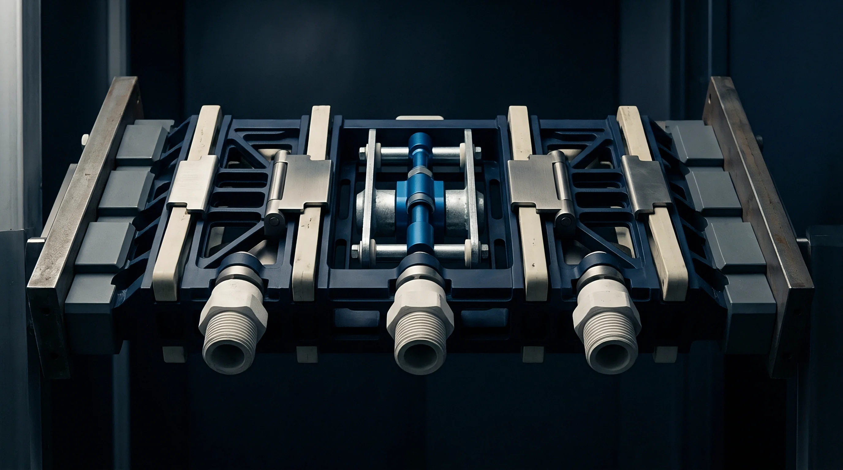
How Does Gate Geometry Accelerate Fiber Fracture?
Sharp entry angles and short land transitions concentrate viscous dissipation within tiny melt volumes. Submerged pin gates and tunnel gates force dramatic stream contractions over very short flow distances. These geometry transitions induce extensional shear forces that snap rigid glass fibers before full alignment occurs.
Implementing a generous entry radius between 15 and 30 degrees smoothly accelerates the melt, mitigating extensional fiber breakage.
Submerged gates generate high shear stress along gate tips during part ejection. The mechanical shearing action during tool opening breaks gate vestiges, but continuous fiber dragging chips away the sharp steel edges of the gate orifice. Gate land length also plays an essential role in preserving fiber length.
A gate land length between 0.8 mm and 1.2 mm balances pressure drop with structural fiber preservation, preventing excessive shear duration.
An engineering team seeking to optimize gate geometry and minimize fiber length reduction adheres to the following sequential protocol:
- Calculates volumetric flow rates and sets gate geometry to limit peak shear rates below 30,000 reciprocal seconds.
- Applies a 25-degree lead-in taper from the runner channel to the gate land to minimize extensional shear stress concentrations.
- Hardened steel resists high friction.
- Selects a fan gate or edge gate layout in place of tunnel or pin gates for fiber reinforced resins exceeding 25 percent loading.
- Configures gate land length to exactly 1.0 mm to balance pack pressure transmission with minimal shear history exposure.
- Applies chemical vapor deposition titanium aluminum nitride coating directly to replaceable gate inserts prior to mold trial runs.
Shorter runner channels with generous transition radii preserve fiber length far more effectively than elevated melt temperatures inside the barrel.
Toolmakers routinely claim that fiber attrition stems entirely from barrel shear settings rather than restrictive runner transitions or aggressive gate land step-downs.


Allowance
Tooling design specifications incorporate dimensional wear reserves to offset gradual steel recession. Establishing precise tooling wear allocations guarantees that part dimensions remain within drawing tolerances throughout the contracted tooling lifecycle. Strategic selection of tool steel alloys, heat treatments, surface coatings, and modular insert strategies isolates high-wear zones, ensuring efficient maintenance without necessitating full mold rebuilds.

Steel Alloy Selection and Protective Coatings
Selecting powder metallurgy tool grades drastically extends production longevity under abrasive compound exposure. Traditional pre-hardened steels like P20 (1.2311) offer easy machinability but succumb rapidly to abrasive wear from fiber filled resins, degrading after fewer than 50,000 cycles. Standard tool steels such as H13 (1.2343) or 420 stainless steel (1.2083) hardened to 52-54 HRC provide intermediate resistance, suitable for moderate production runs up to 250,000 cycles.
High-volume production environments processing abrasive resins demand high-alloy powder metallurgy steels such as CPM-10V, Vanadis 4 Extra, or Elmax hardened above 58 HRC. Hardened steel resists high friction. These materials contain high volume fractions of vanadium and chromium carbides that resist micro-plowing by glass fibers.
Supplementing premium steel substrates with surface treatments further enhances wear resistance. Physical vapor deposition (PVD) coatings, such as Titanium Nitride (TiN), Titanium Aluminum Nitride (TiAlN), or Diamond-Like Carbon (DLC), create ultra-hard protective barriers with surface hardness values exceeding 2,500 HV.
| Tooling Alloy Grade | Hardness (HRC) | Surface Coating | Coating Hardness (HV) | Expected Gate Shot Life |
|---|---|---|---|---|
| P20 Steel (1.2311) | 30-32 | None | ~320 | 25,000 |
| H13 Tool Steel (1.2343) | 50-52 | None | ~540 | 150,000 |
| 420 Stainless (1.2083) | 52-54 | Nitride | ~1,000 | 300,000 |
| CPM-10V Powder Steel | 58-60 | TiAlN PVD | ~3,000 | 1,000,000 |
| Tungsten Carbide Inserts | 72-75 | CVD Diamond | >8,000 | 3,000,000 |

Dimensional Tolerance Drifts and Maintenance Windows
Part wall swelling and flash formation define the operational boundary for core re-machining interventions. As steel erodes at parting lines and shutting faces, internal cavity pressure forces molten resin into micro-gaps, creating flash that exceeds maximum drawing limits (typically 0.03 mm to 0.05 mm). Parting lines flash under load.
Core pins experiencing cross-flow fiber abrasion undergo asymmetrical steel reduction, causing wall thickness variations and part distortion upon ejection.
Modular tooling strategies mitigate wear management expenses by placing small, easily replaceable steel inserts at high-erosion locations, including gates, shut-offs, and core pin tips. Coating failures occur at corners. Instead of re-machining or welding an entire cavity block, technicians swap pre-fitted tungsten carbide or CPM-10V inserts during routine maintenance windows.
This modular approach preserves baseline cavity alignment while maintaining component dimensions across multi-million shot production campaigns.
To maximize tool life when running fiber reinforced compounds, tooling buyers integrate several material selection parameters into early design specifications:
- Modular Gate Inserts Core blocks incorporate independent gate inserts crafted from powder metallurgy steel, enabling isolated replacement without modifying primary cavity plates.
- PVD Surface Passivation High-stress flow channels receive a 3 to 5 micrometer TiAlN coating layer to prevent direct steel contact with abrasive glass filaments.
- Guided Ejection Busings Precision guided ejector systems prevent lateral pin drift, minimizing parting line scoring and reducing localized pin wear during high-speed continuous ejection.
- Interlocking Core Alignment Tapered side locks align core and cavity halves prior to mold closure, preventing wiping wear on shut-off surfaces during clamping.
Incorporating ISO 19900 wear allowance limits into the supply agreement transfers financial liability for mid-lifecycle insert refurbishments directly to the molding contractor.


Audit
Empirical verification protocols evaluate physical core loss and structural property retentions simultaneously. Establishing rigorous verification workflows guarantees that tool degradation remains within contractually agreed parameters before part quality suffers. Inspection combines non-destructive dimensional profiling of worn steel surfaces with destructive mechanical testing of molded components.

Non Destructive Inspection and Micro Computed Tomography
Industrial X-ray imaging reveals internal filament orientation and volumetric void distributions inside molded specimens. Micro-computed tomography (micro-CT) resolves internal fiber length distributions without requiring resin burn-off or matrix digestion. Micro-CT scans resolve fiber orientation.
Scanning molded tensile coupons at resolutions below 2 micrometers enables full three-dimensional reconstruction of individual glass filaments, quantifying aspect ratio distribution changes as gates erode.
Laser profilometry and optical coordinate measuring machines (CMM) record physical steel loss inside cavity blocks. Optical profiling measures gate land depth increases, runner profile alterations, and parting line recession without physical contact that could mar polished tool steel. Comparing point-cloud scan data against original CAD geometry surfaces accurate wear contours, providing early warning when erosion approaches maximum dimensional allowance limits.

Mechanical Coupon Verification Protocols
Standardized tensile dogbones molded alongside production parts yield direct structural quality measurements. Molds incorporate sacrificial test coupon cavities fed directly from the primary runner system. Testing coupons according to ISO 527 (tensile testing) and ISO 179 (Charpy impact testing) at regular production intervals tracks property degradation over shot count milestones.
Thin wall sections experience wear.
A statistical quality control program sets alert limits at a 5 percent drop in tensile strength and action limits at a 10 percent drop. Breaching action limits triggers mandatory tool inspection, insert replacement, or gate re-machining. Burn-off testing per ISO 1172 verifies fiber weight percentage, ensuring that mechanical drop-offs stem from physical fiber attrition or shear damage rather than resin lot variations or fiber settling inside plasticizing units.
Surface roughness increases at the gate land serve as an early indicator of fiber fracture and impending tensile modulus loss in molded components.
Quality engineers execute comprehensive wear auditing through a systematic verification checklist across production campaigns:
- Gate Dimension Scanning Optical profiling captures gate width, depth, and land length every 50,000 shots to quantify volumetric steel loss against CAD reference baselines.
- Tensile Coupon Destruction Destructive testing of ISO 527 Type 1A tensile bars determines ultimate tensile strength, flexural modulus, and elongation at break.
- Fiber Matrix Burn Off Thermal degradation of matrix resins at 600 degrees Celsius isolates glass fibers for automated optical image analysis of length distributions.
- Parting Line Flash Measurement Profilometer measurements track parting line recession and flash height across critical seal shut-off zones.
It remains uncertain whether inline ultrasonic acoustic emission sensors can reliably differentiate between matrix micro-cracking and fiber-matrix debonding during high-speed cavity filling.


Amortization
Financial management of tooling assets hinges on allocating maintenance capital against total produced component volume. Fiber reinforced materials accelerate wear, shortening component lifecycle intervals and shifting traditional tooling cost dynamics. Assigning refurbishing expenses, insert replacement schedules, and mechanical reserve funds into initial piece-part pricing prevents margin erosion and protects project return on investment.

Structural Responsibility and Refurbishment Cost Allocation
Contractual agreements assign financial liability for cavity wear based on shot count milestones and material aggressiveness. Turnkey manufacturing contracts explicitly state whether the tooling owner or the molding facility funds mid-campaign insert swaps, gate refurbishments, and protective coating reapplications. Unclear wear allocation leads to protracted disputes when parts exhibit dimensional drift or structural strength failures prior to reaching guaranteed shot lives.
Tooling guarantees must define specific resin formulations and fiber loading percentages. Refurbishment costs scale with cavity count. A tool guaranteed for 1,000,000 cycles using unfilled polypropylene will fail prematurely at 150,000 cycles if operated with 40 percent glass fiber reinforced polyphenylsulfone (PPS).
Contracts specify wear reserve line items, setting aside a fraction of a cent per molded part to generate an escrow fund allocated solely to preventive tool maintenance and insert replacement.

Piece Part Pricing Adjustment and Tooling Life Accounting
Unit prices often bundle a tooling reserve fee to offset expected mid-campaign steel replacement expenses. To build an accurate financial model, engineers calculate total cost per shot including routine maintenance overheads, tooling insert replacement costs, and lost machine time during refurbishments.
Consider a 4-cavity mold producing automotive structural brackets from 30 percent carbon fiber reinforced polyetheretherketone (PEEK-CF30). Initial tooling non-recurring engineering (NRE) costs $180,000 using CPM-10V high-wear powder steel gate inserts. High injection pressures accelerate scoring.
The initial gate inserts carry a rated life of 200,000 shots before erosion breaches part drawing tolerances, requiring modular insert replacement.
| Cost Component | Baseline Unreinforced Resin | 30% Glass Reinforced Resin | 40% Carbon Reinforced Resin |
|---|---|---|---|
| Initial NRE Capital Cost | $120,000 | $150,000 | $180,000 |
| Guaranteed Tool Shot Life | 1,000,000 | 500,000 | 300,000 |
| Insert Refurbishment Interval | None | 150,000 shots | 100,000 shots |
| Refurbishment Cost Per Cycle | $0.00 | $0.025 | $0.060 |
| Tooling Maintenance Reserve Per Part | $0.003 | $0.018 | $0.045 |
| Amortized Tooling Cost Per Part | $0.033 | $0.093 | $0.195 |
In this high-performance application, each insert refurbishing event costs $12,000, including high-alloy steel fabrication, coating reapplication, and bench fitting. Thermal gradients alter residual stress. Over a total planned production campaign of 600,000 shots (2,400,000 completed components), two mandatory insert replacement cycles take place, adding $24,000 in direct maintenance costs.
Machine downtime during maintenance consumes 40 hours per intervention at an amortized press rate of $150 per hour, contributing an additional $12,000 in lost production capacity.
The total lifecycle wear allocation calculation sums initial tooling capital ($180,000), maintenance refurbishments ($24,000), and press downtime opportunity costs ($12,000), reaching $216,000. Amortizing $216,000 across 2,400,000 finished parts yields a tooling asset cost of $0.09 per part. Dimensional creep exceeds drawing tolerances.
By structuring the piece-part price with a designated $0.09 tooling wear reserve, the buyer and manufacturer maintain clear financial responsibility, ensuring timely tooling refurbishments without interrupting component delivery schedules.
Accounting for cumulative shot counts against pre-agreed wear reserves establishes a predictable capital expenditure schedule for tool replacement before structural component degradation compromises production yield.