Quantifying Transient Battery Voltage Drops during High Current Active Receiver Pulse Sequences
Dynamic battery impedance causes severe transient voltage drops during receiver pulses, requiring calibrated capacitance to prevent MCU brownout resets.

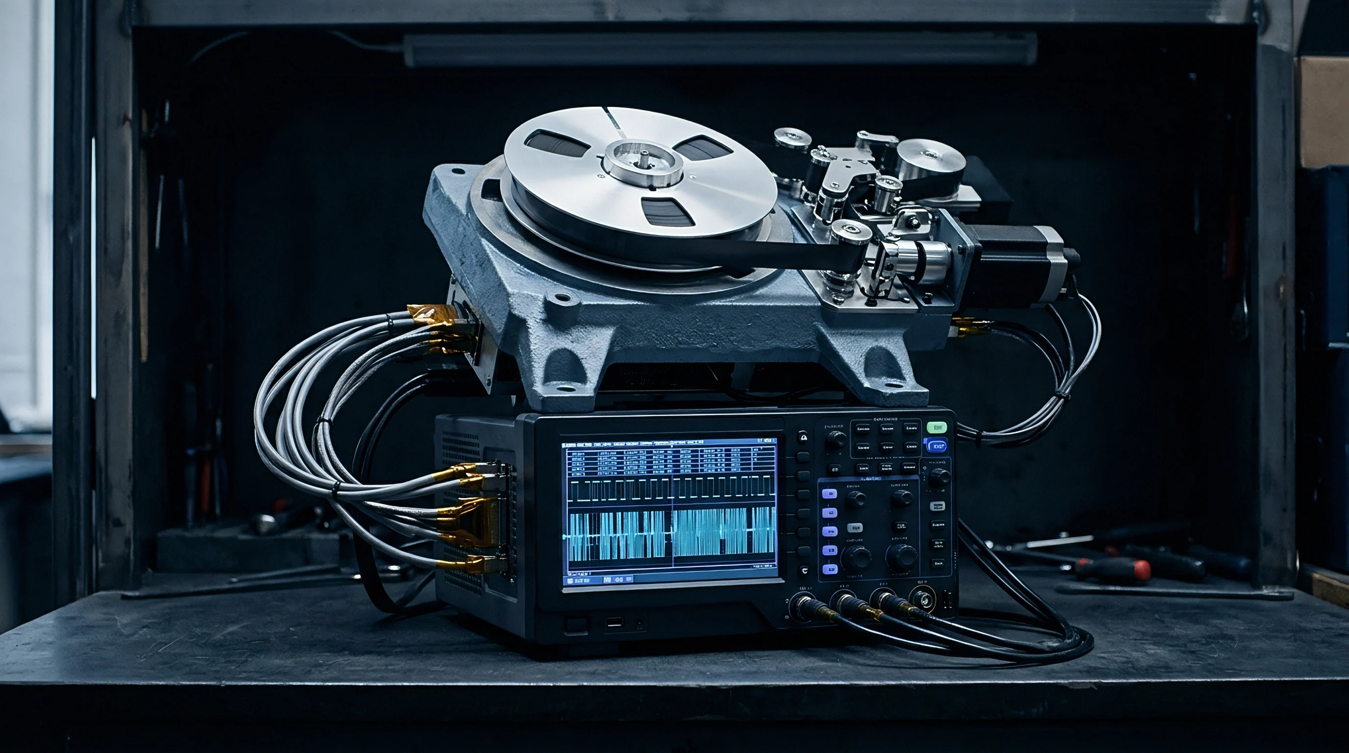
Rail
Clamping a high-speed digitizer across an unbuffered lithium coin cell shows the rail drop immediately once the RF synthesizer locks. Modern transceiver silicon pulls sharp step-function loads during receive states that primary chemistries struggle to support. The low-noise amplifier, mixer, and high-speed analog-to-digital converters energize in microseconds, drawing between 12 and 85 milliamperes depending on modulation bandwidth and carrier frequency.
The resulting terminal voltage drop stems from two distinct effects: instantaneous resistive drop across the cell’s internal resistance, followed by concentration polarization as active species deplete at the electrode faces.
Design teams often spend weeks tuning transmit power while treating the receive budget as negligible. Yet long packet preambles, wide channel scans, and frequent listen windows hold the radio in high-drain reception long enough to drag the rail below the microcontroller’s power-on reset threshold, causing unrecoverable system crashes.
Transient dips below 1.95 volts lasting longer than 15 microseconds trigger uncommanded brownout resets across ARM Cortex-M0+ architectures operating at 3.0 volts nominal.
Microcontroller supervisors monitor input potential using internal brownout detector circuits. These analog comparators measure the battery feed against an internal bandgap reference; if the supply rail pierces the threshold, the supervisor asserts a hard reset, freezing the core and clearing peripheral registers.

Brownout Thresholds during Demanding Baseband Processing
Modern wireless chipsets rely on digital demodulators that draw sudden bursts of current during baseband filtering. Stepping from a sleep current under 2 microamperes to active baseband reception above 18 milliamperes produces steep di/dt edges. On an unregulated cell with a nominal 3.0-volt open-circuit potential, that step can pull the rail below 2.0 volts in less than 4 microseconds.
Once the reset line trips, firmware execution halts instantly. Radio state machines lose track of incoming packets, triggering frame aborts and retransmissions. These repeated receive attempts drain the cell further, worsening terminal sag on subsequent wake cycles.
Many microcontrollers allow setting the brownout detector to lower trip points. Dropping the supervisor down to 1.8 volts squeezes more life from depleted cells, but it eats away the margin protecting memory integrity. Internal flash writes and retention flip-flops need a minimum potential barrier to preserve bit states; operating near that line risks silent register corruption whenever radio reception coincides with sensor logging.

Instantaneous Impedance and Peak Current Pulses
Battery performance under pulsed loading looks nothing like standard continuous discharge curves. Electrochemical cells present a complex internal impedance made up of ohmic resistance, charge-transfer resistance, and Warburg diffusion effects. The purely ohmic contribution includes contact resistance, collector foil conductivity, and bulk electrolyte resistivity.
When the receiver turns on, ohmic impedance drives an instantaneous potential drop governed by Ohm’s law. Charge-transfer resistance and double-layer capacitance then produce an exponential decay over tens of microseconds. If the receive window stretches beyond a few milliseconds, diffusion limits in the electrolyte cause an additional concentration polarization droop.
This cumulative loss pulls the supply bus below operational limits.
Overlooking this dynamic sag causes premature battery replacements, corrupts non-volatile memory partitions, and triggers hard lockups across deployed industrial sensor fleets.


Chemistry
Primary lithium chemistries behave quite differently under steep milliampere-scale pulses. Lithium thionyl chloride delivers exceptional energy density ~ up to 650 watt-hours per kilogram ~ with negligible self-discharge, which is why it dominates ten-year utility metering. However, storage causes a dielectric passivation layer of lithium chloride crystals to form over the lithium anode.
While that layer protects shelf capacity, it introduces substantial internal resistance during initial current extraction.
Lithium manganese dioxide coin cells form far less passivation, keeping baseline internal resistance relatively low at room temperature. But their impedance climbs steeply near freezing as lithium-ion transport through the organic electrolyte slows down. Thin-film solid-state cells eliminate liquid leakage altogether, yet their ceramic electrolyte layers exhibit high bulk ohmic resistance that caps pulse delivery to single-digit milliamperes.
Ion transport in the solid electrolyte fails to keep pace with instantaneous current demand.
| Cell Chemistry | Nominal Open Circuit Potential (V) | Initial Internal Resistance (Ohms) | Passivated Peak Resistance (Ohms) | Loaded Minimum Terminal Potential (V) | Voltage Recovery Duration (ms) |
|---|---|---|---|---|---|
| Li-SOCl2 (Bobbin Construction) | 3.65 | 28 | 210 | 1.82 | 4.50 |
| Li-SOCl2 (Spiral Construction) | 3.65 | 4.5 | 22 | 2.85 | 0.80 |
| Li-MnO2 (CR2032 Coin) | 3.00 | 18 | 24 | 2.10 | 0.35 |
| Li-FeS2 (Cylindrical 1.5V x 2) | 3.20 | 0.8 | 1.1 | 3.12 | 0.05 |

Passivation Layers in Lithium Thionyl Chloride
Bobbin-type lithium thionyl chloride cells maximize active chemical volume by pairing a solid cylindrical carbon cathode with an outer lithium sleeve. Because the surface area is small relative to the total volume, resting for several months thickens the surface salt layer, pushing internal resistance past 200 ohms.
When the receiver switches on, this impedance can drop terminal potential near zero within microseconds. The current load gradually breaks down the salt barrier through local electro-dissolution, restoring fresh electrolyte contact and lifting the voltage over several milliseconds. But if the receive pulse finishes before that film ruptures, terminal voltage never recovers during the wake interval.
Spiral-wound lithium thionyl chloride cells interleave thin lithium foil and carbon sheets, expanding surface area roughly tenfold. This mechanical structure reduces both initial ohmic resistance and passivated resistance peaks. The trade-off is higher self-discharge, sacrificing storage life for pulse capability.

Electrolyte Mobility under Subzero Operating Temperatures
Temperature dictates ionic conductivity through separator membranes. Below minus 20 degrees Celsius, electrolyte viscosity rises and slows lithium-ion migration. Solvation shells around moving ions tighten, increasing charge-transfer resistance across the electrode interface.
Subzero operation sharply increases equivalent series resistance across the cell.
Coin cells in outdoor enclosures often see their resistance triple overnight in winter. A fresh cell reading 15 ohms at room temperature can easily exceed 75 ohms at minus 30 degrees Celsius. At that impedance, a 25-milliampere receive burst drops 1.875-volt across the cell itself, crashing a 3.0-volt rail down to 1.125 volts.
Repeated high-drain receiver pulses trigger several distinct failure modes:
- Interfacial salt crystallization restricts ion conduction channels through the separator matrix, generating localized hot spots and accelerating local capacity exhaustion.
- Lithium dendrite propagation develops along uneven dissolution zones on the anode foil during repeated pulse relaxation cycles, threatening internal micro-shorts.
- Electrolyte solvent cavitation occurs when high instantaneous current densities induce micro-bubbles of vaporized solvent near the current collectors, severing conductive liquid paths.
- Cathode matrix delamination manifests when repetitive electrochemical volume contraction loosens porous carbon particles from metallic substrate meshes, permanently raising series impedance.
Published nominal capacity ratings apply to continuous discharge below rated thresholds, rather than high-amplitude pulsed profiles.


Waveform
Radio reception draws varying current dictated by front-end architecture and modulation schemes. A sub-GHz or 2.4 GHz receiver rarely pulls a static current while listening; the profile steps through distinct phases: crystal oscillator startup, frequency synthesizer calibration, low-noise amplifier biasing, automatic gain control settling, and digital baseband correlation.
Extended active receive duration directly compounds the total energy burden.
Each stage steps the rail load. Crystal startup pulls between 1 and 3 milliamperes across several hundred microseconds. Synthesizer calibration follows, with brief spikes up to 8 milliamperes while voltage-controlled oscillators center their ranges.
Once the analog front-end turns on fully, the rail sees active receive current, generating the steepest transient edge on the battery.
| Protocol and Modulation | Channel Bandwidth (kHz) | Peak Receiver Current (mA) | Active Window Duration (ms) | Repetition Interval (s) | Calculated Total Energy (mJ) |
|---|---|---|---|---|---|
| BLE 5.0 Coded PHY (S=8) | 2000 | 14.5 | 42.0 | 1.28 | 1.83 |
| LoRa CAD (SF12, BW125) | 125 | 11.2 | 34.5 | 4.00 | 1.16 |
| IEEE 802.15.4 (2.4 GHz O-QPSK) | 5000 | 18.0 | 3.8 | 0.50 | 0.21 |
| LTE-M Paging eDRX (Band 20) | 1400 | 125.0 | 82.0 | 10.24 | 30.75 |
| NB-IoT NPDCCH Search Space | 200 | 85.0 | 128.0 | 20.48 | 32.64 |

Which Receiver Operating Modes Provoke Maximum Sag?
Continuous receive windows cause significant concentration polarization because diffusion gradients deplete active ions near the electrodes. In Bluetooth Low Energy systems, extended discovery forces scanning across three primary advertising channels (37, 38, and 39). Under Long Range Coded PHY modes using eighth-rate forward error correction, symbol duration increases eightfold, lengthening the listen window to tens of milliseconds.
Cellular IoT transceivers running LTE-M or NB-IoT present an even harder transient load. Although transmission can hit 450 milliamperes at peak output, downlink processing requires keeping the receiver active across multiple subframes. During extended discontinuous reception wakes, the modem processes radio resource control signaling, system information blocks, and paging channels, sustaining receiver currents above 100 milliamperes for 50 to 150 millisecond spans.
Prolonged current draw depresses terminal voltage significantly. The initial ohmic drop gives way to a downward slope as active ions near the cathode deplete, and the voltage keeps dropping until the baseband processor shuts down the radio or the microcontroller browns out.
System specifications adhering to ETSI EN 300 220-1 require strict listen-before-talk receiver intervals that lock transceivers into high-drain carrier sense windows for at least 5 milliseconds before any channel access.

Preamble Hunting versus Continuous Carrier Sensing
Sub-GHz protocols like LoRa use channel activity detection to limit receiver on-time. A detection cycle enables the receiver for roughly one and a quarter chirp symbols plus calibration overhead. During this window, the analog front end samples the RF channel while the baseband runs a fast Fourier transform correlation to identify matching preambles.
The receiver draws steady active current throughout this listening window.
If energy correlates, the radio remains in continuous reception to receive the payload; if not, it drops back to sleep. The transient effect on the battery rail depends on the duty cycle between listening and sleeping. Tight polling intervals build up internal cell polarization and heat, worsening voltage sag over time.
Receiver profile evaluation focuses on four hardware and protocol variables:
- Channel activity polling frequency determines whether battery concentration polarization completely relaxes between successive receiver bursts, preventing progressive voltage decline.
- Baseband clock frequency scaling dictates peak digital core current, where operating at 64 megahertz doubles dynamic switching draw compared to 32 megahertz.
- Intermediate frequency sampling bandwidth governs analog filter power, with wider channels requiring higher operational amplifier bias currents in the receiver front end.
- Automatic gain control loop damping creates secondary current ripple when aggressive gain hunting toggles internal attenuators during burst preamble detection.
Under Clause 6.4 of standard master supply agreements for industrial wireless telemetry nodes, components failing to complete complete listen-before-talk sequences within specified rail ripple limits forfeit production lot acceptance and trigger full supplier rework obligations.


Capacitance
Placing local energy storage right at transceiver supply pins buffers the battery from rapid receive transients. Sizing these capacitors involves balancing charge capacity, equivalent series resistance, board footprint, and quiescent leakage. Multilayer ceramic capacitors provide extremely low equivalent series resistance ~ often under 10 milliohms ~ delivering immediate charge during nanosecond switching edges.
However, their volumetric density is modest, making parallel banks larger than 100 microfarads impractical in compact sensor housings.
Tantalum polymer and aluminum electrolytic capacitors provide far more capacitance, scaling into the thousands of microfarads. Their equivalent series resistance sits between 50 and 500 milliohms, introducing measurable internal drop during milliampere-scale pulses. Electrochemical double-layer capacitors offer massive capacitance past hundreds of millifarads, but bring higher equivalent series resistance and parasitic leakage currents that eat into primary battery life.
Effective capacitance drops sharply under applied DC bias.

Will Decoupling Capacitance Suppress Peak Transients?
Decoupling performance depends on how much charge the capacitor loses over the duration of the pulse. When the radio turns on, the local capacitor delivers the bulk of the initial current until its voltage drops to match the loaded cell. Once the radio returns to sleep, the cell recharges the capacitor.
Determining capacitance requires balancing allowable droop, pulse current, duration, and cell impedance. For instance, consider a circuit drawing 30 milliamperes across a 15-millisecond window with an allowable droop of 300 millivolts:
The total electrical charge required by the pulse equals current multiplied by duration: 30 milliamperes multiplied by 15 milliseconds yields 450 microcoulombs. If the capacitor supplied this charge alone without battery assistance, the required capacitance would equal charge divided by allowable voltage drop: 450 microcoulombs divided by 0.3 volts yields 1500 microfarads. In practice, the primary battery continuously feeds current into the shared junction throughout the pulse, reducing necessary capacitor size according to the battery internal resistance and the resulting circuit time constant.
DC bias derating in Class II ceramic parts must be factored into calculations. A 100-microfarad X5R capacitor rated at 6.3 volts loses up to 65 percent of its capacitance at a 3.0-volt DC operating point. Operating at high temperatures degrades dielectric performance even further, cutting usable capacitance.
| Capacitor Technology | Capacitance Range (uF) | Equivalent Series Resistance (mOhm) | Quiescent Leakage Current (uA) | Operating Temperature Span (C) | DC Bias Derating Impact |
|---|---|---|---|---|---|
| MLCC (Class II X5R/X7R) | 10 – 220 | 5 – 25 | 0.05 – 0.20 | -55 to +125 | Severe (40% to 70% loss) |
| Tantalum Polymer | 47 – 1000 | 35 – 150 | 2.0 – 15.0 | -55 to +105 | Negligible (under 5% loss) |
| Hybrid Layer Capacitor (HLC) | 50000 – 500000 | 100 – 500 | 1.5 – 8.0 | -40 to +85 | None |
| EDLC Supercapacitor | 100000 – 2000000 | 200 – 1500 | 3.0 – 25.0 | -40 to +65 | None |

Supercapacitor Equivalent Series Resistance and Leakage
Pairing supercapacitors with high-impedance lithium thionyl chloride cells absorbs big transmit spikes, but creates clear trade-offs during reception. The equivalent series resistance of small coin-sized supercapacitors sits between 100 and 500 milliohms. While that is much lower than a passivated primary cell, it still drops 25-millivolt under a 50-milliampere load step.
Parasitic capacitor leakage steadily consumes cell capacity during long sleep intervals.
Leakage current remains the primary concern. Small supercapacitors continuously pull between 2 and 15 microamperes depending on operating temperature and rail voltage. For a remote sensor targeting a ten-year lifespan on an AA primary cell, sleep current usually needs to stay under 3 microamperes.
Adding a supercapacitor can quadruple background consumption, burning through battery reserves merely to buffer occasional receive bursts.
Sizing buffer stages requires balancing these competing constraints:
- Map instantaneous receiver current profiles with microsecond-level time resolution to identify peak drain amplitude and integrated charge across each discrete functional phase.
- Calculate maximum permissible bus impedance by dividing allowable supply rail droop by the peak receiver step current, establishing an upper boundary for combined battery and capacitor ESR.
- Select dielectric technologies that maintain required effective capacitance after applying real-world DC bias derating and worst-case subzero thermal degradation factors.
A larger capacitor always shortens battery life through parasitic leakage when sleep intervals exceed active intervals.


Benchmark
Accurate measurement of transient terminal droop requires high-bandwidth dynamic load testing under controlled conditions. Standard bench power supplies hide cell dynamics behind internal regulation loops and large output capacitors. Powering a wireless node straight from bench equipment will mask brownout issues that appear when the board runs on primary cells in the field.
Fast step loads reveal internal impedance issues that steady-state discharge masks.
Specialized battery emulators mimic chemical sources by altering output voltage based on configured internal resistance and capacitance values. While programmable emulators handle static resistance well, they rarely replicate temperature-driven ion depletion or passivation layer breakdown seen in physical lithium cells.
Direct hardware testing relies on running production cell lots inside thermal chambers. Low-inductance current shunts or Hall probes are placed inline with the battery lead, while active, high-impedance oscilloscope probes measure potential directly at the microcontroller power pins to separate rail collapse from ground bounce.
Oscilloscope input bandwidth must span at least 20 megahertz when capturing receiver transient voltage dips to prevent low-pass filtering of microsecond brownout spikes.

Direct Current Oscilloscope Probing across Active Sequences
Tracking rapid rail dips requires careful trigger setup. Running a high-bandwidth scope in DC-coupled deep memory captures open-circuit levels and active load troughs side by side. Setting single-shot edge triggers on the falling edge of the supply rail catches the lowest point during preamble detection.
Improper triggering can miss the narrowest point of the transient dip entirely.
Ground loops are the most frequent source of measurement error in rail characterization. Standard 10x passive probe ground leads act as antennas for radiated RF energy from nearby antenna matching networks, showing up as high-frequency noise riding on the supply trace. Using coaxial probe adapters with ground spring contacts soldered right against decoupling capacitors removes that RF pickup.
Dynamic voltage dips during fast load steps often exceed predictions based solely on DC resistance.

Pulsed Profiling under Real Operating Depletion
Battery impedance shifts significantly with state of charge. A fresh lithium manganese dioxide cell showing 18 ohms of internal resistance stays relatively stable through its first 30 percent of discharge. Past 70 percent depth of discharge, cathode chemistry changes and resistance climbs above 60 ohms.
Qualifying dynamic voltage margins solely on fresh cells produces dangerously optimistic expectations.
A reliable test plan pre-discharges test cells to 20, 50, and 80 percent of rated capacity before running transient pulse characterization. These depleted cells are then tested across temperature chambers running at minus 40, zero, and plus 60 degrees Celsius.
Subzero temperatures compound the problem by raising cell impedance while lowering output potential.
Sudden supply dropouts can leave peripheral registers and internal states corrupted.
Certifying that passivation breakdown dynamics under irregular polling will prevent uncommanded resets across thousands of field units without decade-long validation trials remains a primary qualification challenge.