Radio Equipment Directive Host Integration Testing Procedures and Technical File Assembly
CE module approvals do not cover host integration; host manufacturers must execute physical delta testing and compile a full RED Technical File.


Scope
Placing an integrated radio product on the European market binds the host manufacturer to full legal accountability under the Radio Equipment Directive 2014/53/EU. Integrating a pre-certified radio module carrying CE mark documentation does not transfer market responsibility to the module vendor. The final combination of the host device and the radio transmitter creates a new radio equipment entity under EU law.
Customs authorities and national market surveillance agencies audit the completed assembly rather than the internal component sub-assemblies. The host integrator signs the EU Declaration of Conformity as the sole responsible party.
Sourcing an off-the-shelf wireless module alters product development timelines. Suppliers publish operational parameters captured inside ideal test fixtures. Those parameters reflect standalone performance in open air or on designated reference boards.
Once the module mounts inside a dense industrial chassis alongside switched-mode power supplies, touchscreens, and high-speed data buses, the electromagnetic profile shifts. The original certificate carried by the module vendor serves solely as supporting technical data. It does not guarantee compliance for the final finished host.

Host Integrator Legal Status under Directive
The Radio Equipment Directive eliminates the concept of inherited module compliance. Article 3 mandates that all radio equipment protects health and safety, maintains electromagnetic compatibility, and uses the radio spectrum efficiently. When a non-radio host incorporates a radio module, the entire host becomes radio equipment.
The entity placing the complete product on the market assumes all legal obligations of a manufacturer. The regulatory filing list below defines host integration responsibilities.
- Supplier Technical Dossier Audit requires collecting original module test reports, antenna specifications, grants, and operational instructions to verify that test conditions match host operational boundaries.
- Host Integration Gap Analysis establishes which essential requirements remain fully covered by existing module credentials and which parameters require physical delta testing in a laboratory.
- Combined Equipment Evaluation applies ETSI EG 203 367 guidelines to determine structural electromagnetic interaction between host electronics and the embedded radio sub-assembly.
- Declaration of Conformity Drafting consolidates harmonised standard references covering safety under Article 3.1a, electromagnetic compatibility under Article 3.1b, and spectrum usage under Article 3.2.
Compliance files sit in European storage locations. Market surveillance authorities request complete technical documentation during random audits or customs blocks. Failure to produce a compliant host-level technical file within ten working days triggers sales bans, mandatory inventory recalls, and administrative fines across all European Union member states.

Commercial Exposure in Sourcing Approved Modules
Buying an approved module reduces direct design risks but shifts financial risk toward final verification. Engineering teams budget for module integration without accounting for required physical measurement campaigns. Laboratory bookings, chamber time, and engineering corrections represent direct cash outlays before market launch.
Sourcing contracts omitting module vendor engineering support leave host integrators paying full laboratory rates during troubleshooting cycles.
Antenna selection alters legal status directly. Modifying the original module antenna design invalidates existing transmitter test reports. Alternate trace antennas, external coax runs, or custom enclosure notches void original RF exposure calculations and spurious emission test data.
Sourcing teams paying premium module costs discover that minor physical enclosure alterations trigger complete re-testing of Article 3.2 spectrum requirements.
Unverified module documentation delays product launches by two to three months. Internal development schedules break when testing laboratories reject incomplete supplier test reports. Purchasing departments must demand full, unredacted test reports directly from module vendors before locking host circuit designs.

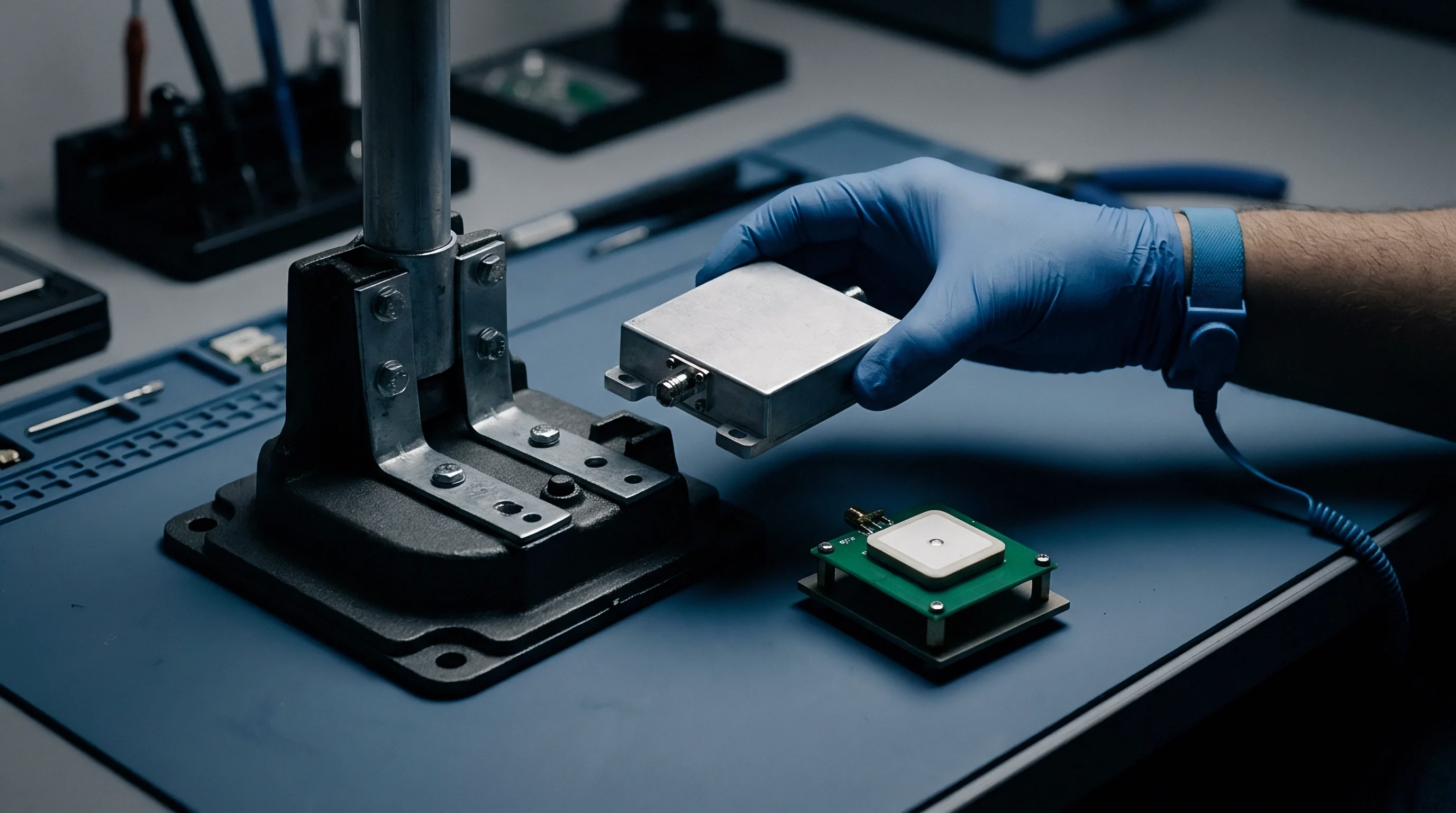
Clamp
Physical mounting methods dictate high-frequency electromagnetic performance. Mounting a module onto a host board alters grounding paths, return currents, and parasitic coupling. The host mainboard acts as an extended ground plane, changing the directivity and efficiency of embedded antennas.
RF currents spill across board edges, exciting host cable harnesses and mechanical metal frame elements. Physical integration testing verifies that mechanical clamps, board standoffs, and ground springs perform under continuous operational stress.
Enclosure materials alter electromagnetic boundaries. Metallic housings, conductive paints, and internal structural brackets alter local field distributions around transmitter circuits. RF energy reflects back into the module matching network, altering transmitter output power and generating unintended intermodulation products.
Microscopic gaps between chassis panels create slot antennas that radiate internal digital clock noise into restricted radio frequency bands.

Physical Coupling and Ground Plane Disruption
Board-to-board interconnects introduce parasitic inductances into RF return paths. High-density headers without ground pins surrounding signal lines act as loop radiators. Radiated emissions increase sharply when high-speed data interfaces like USB 3.0, PCIe, or MIPI CSI operate adjacent to unshielded radio circuitry.
Solder joint fatigue on heavy mechanical clamps degrades grounding low-impedance pathways over operational product lifetimes.
Placing an unshielded host cable harness within fifty millimetres of an integrated antenna elevates radiated noise floors by up to eighteen decibels across low-power telemetry bands.
Thermal management elements introduce unexpected RF paths. Large aluminum heatsinks attached to host processors collect ambient RF energy from the internal antenna. These heatsinks reradiate energy as secondary radiators, degrading spurious emission margins.
Dielectric isolation pads between power semiconductors and chassis clamps introduce parasitic capacitance that conducts high-frequency switching noise into the host frame ground.

Power Distribution Network Impedance Shifts
Radio modules demand dynamic current during transmission bursts. Switched-mode power supplies on the host mainboard introduce ripple and voltage droop onto the module power supply rails. Excessive ripple modulates transmitter power amplifiers, generating unwanted sideband emissions outside allocated channel bandwidths.
Host decoupling capacitors must present low impedance across fundamental and harmonic transmitter frequencies.
Power distribution network impedance changes with board temperature and component tolerances. Dynamic loads from host processing units pull transient currents that degrade radio receiver sensitivity. Measurement procedures evaluate power line conducted emissions and radio performance under worst-case operational processor loads.
Table 1 outlines the host evaluation matrix required when integrating modules into diverse host configurations.
| Integration Scenario | Physical Modification | Article 3.1a Impact | Article 3.1b Impact | Article 3.2 Impact |
|---|---|---|---|---|
| Identical Module and Antenna | None, Plastichousing | Document Review | Full Host EMC Scan | Targeted RSE Spot-Check |
| Alternative Antenna Gain | Higher Directivity Antenna | Recalculate MPE/SAR | Full Host EMC Scan | Full Radiated RF Testing |
| Metallic Host Chassis | Shielded Enclosure | MPE Near Metal Frame | Enclosure Port Immunity | Spurious Emission Delta Scan |
| Co-located Radios | Multiple Module Integration | Combined RF Exposure | Intermodulation EMC Scan | Intermodulation Radiated RSE |
The module vendor always claims their certificate covers every integration path, but the chamber turntable proves otherwise after two hours of scanning.


Spectrum
The Radio Equipment Directive organizes technical verification under three distinct pillars within Article 3. Article 3.1a addresses electrical safety and human exposure to electromagnetic fields. Article 3.1b mandates electromagnetic compatibility, preventing interference with adjacent electronic equipment and establishing immunity against external disturbances.
Article 3.2 governs effective radio spectrum utilization, preventing harmful interference to licensed radio services.
Determining applicable standards relies on the official list of Harmonised Standards published in the Official Journal of the European Union. Products tested against superseded standards lose presumption of conformity automatically. Host integrators must track standard transition periods to ensure technical files remain valid throughout product commercial lifespans.

Assessment Framework under Harmonised Standards
Harmonised standards set specific measurement methods, frequency limits, and receiver performance criteria. Under Article 3.1a, electrical safety assessment follows EN 62368-1 for audio, video, and information technology equipment. Human exposure evaluations use EN 62209-2 or EN 50566 for portable host equipment operated within twenty centimetres of the human body.
Stationary host equipment uses EN 62311 or EN 50385 to evaluate Maximum Permissible Exposure (MPE) thresholds.
Article 3.1b demands compliance with the EN 301 489 series. EN 301 489-1 defines common technical requirements, while specific parts like EN 301 489-17 apply dedicated tests for wideband data systems. Host digital circuitry gets tested under EN 55032 for emissions and EN 55035 for immunity.
Combining host digital functions with radio transmitters creates a multi-standard evaluation framework.
Harmonised standard EN 301 489-1 Clause 7.1 establishes that host digital emissions must satisfy combined equipment limits during active radio transmit and receive operational cycles.

Combined Radio Equipment Conformity Assessment
Integrating multiple transmitter modules inside a single host creates a multi-radio system. ETSI EG 203 367 establishes technical principles for evaluating combined radio equipment. Radios operating simultaneously generate intermodulation products caused by non-linear mixing in output stages or host electronic junction points.
Testing laboratories measure these intermodulation products during active simultaneous transmission mode.
Assessment requirements vary based on transmitter frequency separation and simultaneous operation modes. The technical checklist below highlights key documentation components needed for multi-radio technical construction files.
- Intermodulation Risk Analysis documents expected operational frequency combinations and predicts mixing products falling into restricted frequency bands.
- Simultaneous Exposure Calculation sums the field strength or Specific Absorption Rate ratios of all co-located transmitters to ensure values stay below unit threshold.
- Host Receiver Blocking Verification measures receiver desensitization caused by broadband noise generated by adjacent internal transmitters and host processors.
- Spurious Emission Combination Search scans harmonic interactions occurring when multi-band transmitters broadcast concurrently at maximum rated output power.
Standard purchase order terms must specify that module suppliers guarantee trace layout compliance with their internal reference design guidelines: “The supplier confirms that module RF performance meets EN 300 328 limits provided host board implementation matches reference layout document rev 2.1 exactly.”


Scan
Radiated Spurious Emission (RSE) testing represents the most failure-prone phase of host integration verification. High-frequency signals escape through mechanical seams, cable apertures, and printed circuit board traces. The testing campaign measures radiated unwanted emissions across a broad frequency range extending up to the tenth harmonic of the highest internal fundamental frequency.
For a 5 GHz RLAN transmitter, measurements extend to 26.5 GHz or 40 GHz.
Fully or semi-anechoic chambers isolate the unit under test from external radio signals. The test specimen rotates three hundred and sixty degrees on a turntable while a measuring antenna sweeps in height from one to four meters. Testing personnel monitor peak, quasi-peak, and average emissions across horizontal and vertical antenna polarizations.

How Does Host Noise Alter Module Spurious Limits?
Digital electronics on host mainboards emit broadband noise from high-frequency clock signals. Processor cores, memory buses, and power converters generate harmonics that align with radio transmitter frequencies. When this host digital noise mixes with radio fundamental frequencies inside non-linear components, spurious intermodulation products appear above directive limits.
Antenna directivity modifications alter field strength calculations. A module tested with an isotropic omnidirectional antenna passes spurious emission limits easily. Sourcing a high-gain directional antenna for host installation focuses RF energy into narrow angular beams.
Radiated power along the main beam axis increases, pushing previously compliant harmonic levels above standard thresholds.

Anechoic Chamber Execution Sequences
Chamber measurement campaigns follow strict systematic sequences to isolate non-compliant frequencies. The following procedure details the physical verification steps executed during an automated spurious emission scan.
- Mount the fully assembled host product on a non-conductive turntable elevated 0.8 meters for frequencies below 1 GHz and 1.5 meters for frequencies above 1 GHz.
- Connect host input cables and peripheral devices, dressing cable runs to maximize radiated emissions according to standard measurement configurations.
- Configure radio test software to lock the internal transmitter into continuous burst transmission at maximum rated output power on lowest, middle, and highest channel frequencies.
- Perform a rapid pre-scan across the 30 MHz to 1 GHz spectrum, rotating the turntable quickly to identify candidate noise spikes above background thresholds.
- Execute final quasi-peak measurements on identified frequency spikes while varying antenna height between 1 and 4 meters and rotating the turntable 360 degrees.
- Extend automated scans above 1 GHz up to ten times the fundamental frequency, employing peak and average detectors with specified resolution bandwidth filters.
- Repeat complete physical sweeps with co-located host radios broadcasting simultaneously to evaluate combined intermodulation spectrum emissions.
Table 2 provides a typical chamber scan time budget for host equipment containing a 2.4 GHz and 5 GHz dual-band transmitter module.
| Frequency Spectrum | Measurement Type | Detector Configuration | Turntable Rotation | Allocated Hours |
|---|---|---|---|---|
| 30 MHz to 1 GHz | Host & Transmitter Spurious | Quasi-Peak (120 kHz BW) | Continuous 360 degrees | 2.5 Hours |
| 1 GHz to 6 GHz | Transmitter Harmonics | Peak / Average (1 MHz BW) | 15 degree stepping | 3.0 Hours |
| 6 GHz to 18 GHz | High-Frequency Harmonics | Peak / Average (1 MHz BW) | 15 degree stepping | 4.0 Hours |
| 18 GHz to 40 GHz | Extended Spectrum Scan | Peak / Average (1 MHz BW) | Fixed azimuth sweep | 2.5 Hours |
A single unshielded display ribbon cable inside a host chassis can convert 480 MHz clock harmonics into a 4.8 dBuV/m violation at 3 meters, failing RED Article 3.1b compliance.
The unresolved engineering issue remains determining how fast automated spatial scan algorithms can detect intermittent, burst-mode spurious emissions from dynamic cognitive radios without extending chamber residence times beyond commercial viability.


Proof
Assembling the Technical Construction File (TCF) transforms physical test results into legal proof of compliance. Article 10 and Annex III of the Radio Equipment Directive outline requirements for Module A (Internal Production Control). The technical file must describe the design, manufacture, and operation of the radio equipment in clear, unambiguous language.
Storage obligations mandate maintaining this documentation for ten years from the date the last product unit enters European distribution channels.
Relying on supplier statements without raw supporting data invalidates the technical file. Notified Bodies and market surveillance authorities reject generic certificates of compliance that lack underlying measurement curves, test bench block diagrams, and calibration certificates. The host technical file bridges the gap between raw component data and final product integrity.

Technical Construction File Structure and Integrity
A compliant technical construction file contains comprehensive engineering data. The dossier must include full mechanical layout drawings, circuit schematics, bill of materials with safety-critical components highlighted, block diagrams showing internal clock trees, and user manuals carrying required regulatory text. Language translation requirements demand that user instructions and safety material appear in national languages dictated by individual target member states.
Software controls controlling transmitter operation require detailed documentation. Under RED, software or firmware driving radio parameter controls (such as output power, frequency selection, or duty cycle limits) must prevent non-compliant end-user modifications. The technical file details how cryptographic signing or locked bootloaders restrict unauthorized firmware flashing.

Risk Assessment Integration for Combined Equipment
Annex III mandates a formal risk assessment addressing specific operational hazards. The risk analysis evaluates intended deployment environments, potential user misuse, physical proximity to the human body, and multi-radio coexistence hazards. The list below identifies critical failure modes that invalidate a host technical construction file.
- Unmapped Antenna Changes occurs when host assemblies use external antennas with physical gains exceeding original module grant specifications.
- Omitted Exposure Calculations happens when portable host equipment user manuals fail to state required minimum separation distances between antenna and body.
- Missing Software Security Proofs appears when host devices allow users to select non-compliant operating frequencies via open administrative interfaces.
- Outdated Standard Citations happens when the Declaration of Conformity references withdrawn harmonised standards superseded in the Official Journal.
A technical file containing full, unredacted test reports signed by accredited laboratories stands up during market surveillance audits without requiring external Notified Body reviews.


Archive
Signing the EU Declaration of Conformity represents the final legal step before affixing the CE mark and releasing the product for shipment. The signature must belong to a corporate officer or designated representative established within the European Union. By signing, the officer assumes full civil and criminal liability for product compliance across all member states.
Maintaining the archive requires continuous operational procedures. Component obsolescence, alternative component sourcing, and software updates alter product electromagnetic profiles over time. Design changes made on the host mainboard require systematic evaluation against the original technical file through a structured engineering change control protocol.

EU Declaration of Conformity Authorisation Requirements
The EU Declaration of Conformity must follow the structure defined in Annex VI of Directive 2014/53/EU. The document identifies the product through unique serial or model numbers, provides full contact details of the legal manufacturer, and lists every directive applicable to the host device. A single Declaration of Conformity covers all applied directives, including Low Voltage Directive, EMC Directive, and RoHS Directive obligations integrated under the RED framework.
The declaration specifies the precise harmonised standards or technical specifications used to declare conformity. Incorporating a Notified Body under RED Annex IV requires listing the Notified Body name, four-digit identification number, and the Issued EU-Type Examination Certificate number on the final document.

Retest Triggers and Financial Recalibration
Physical hardware modifications force re-assessment of host technical files. Swapping a minor passive component on a host power line rarely affects radio compliance, but replacing a display controller or changing mainboard ground plane layer counts alters electromagnetic performance entirely. Table 3 breaks down testing and administrative expenses associated with assembling and maintaining a compliant RED technical construction file.
| Compliance Phase | Activity Description | Estimated Fee (EUR) | Lead Time (Weeks) |
|---|---|---|---|
| Gap Analysis | Module Dossier & Standard Review | 1,500 – 3,000 | 1 – 2 Weeks |
| Pre-Scan Verification | Chamber Pre-Testing & Debug | 2,000 – 4,500 | 1 Week |
| Full Radiated Testing | Article 3.1b & 3.2 Formal Chamber Scans | 6,000 – 14,000 | 2 – 3 Weeks |
| Safety & Exposure | Article 3.1a EN 62368 & SAR Evaluation | 3,500 – 9,000 | 2 Weeks |
| Notified Body (Optional) | Annex IV EU-Type Examination Review | 2,500 – 5,000 | 2 – 4 Weeks |
| Dossier Maintenance | 10-Year Technical File Archiving | 1,000 – 2,000 | Continuous |
Notified Body reviews cost thousands of Euros but provide zero legal immunity if physical chamber testing later proves the product radiates over directive limits.
Re-testing triggers trigger when component suppliers issue Engineering Change Notifications altering module internal silicon revisions. Firmware changes altering output power, channel access mechanisms, or operational duty cycles require immediate technical file updates and delta scans in accredited chambers before updated host units cross customs borders.