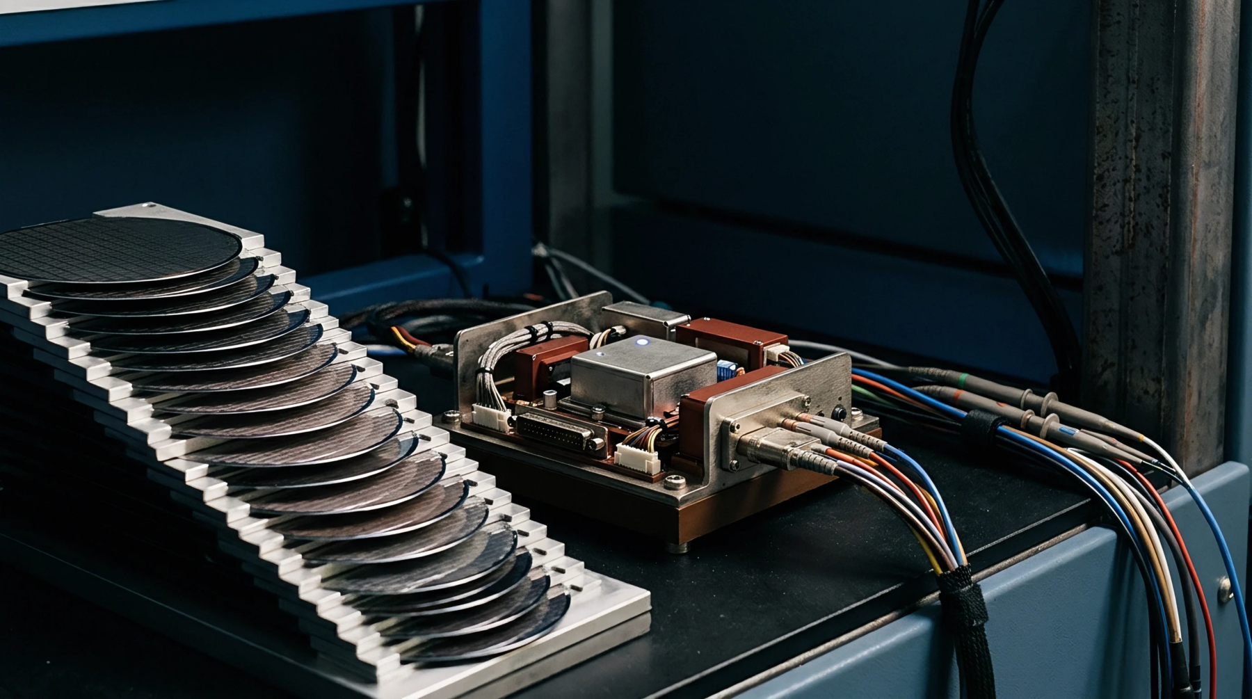
Substrate Conduction Mechanisms in High Resistivity Silicon Wafers
Trap-rich layers eliminate parasitic surface conduction in high-resistivity silicon, suppressing harmonic distortion and insertion loss in RF front-end modules.
Dispersion characteristics quantify the rate at which molecular, ionic or dipole polarizations within an insulating material fail to maintain phase alignment with an applied alternating electric field. In high-frequency printed circuit boards, antenna substrates and potting compounds, dielectric relaxation frequency defines the upper spectral boundary where polar molecules reorient freely, past which the material’s real permittivity plummets while its imaginary permittivity and dissipation factor spike sharply. The physical metric governs operational limits for substrate selection in millimeter-wave communication hardware, ceasing to predict electromagnetic propagation once atomic and electronic polarization mechanisms supersede dipole mechanics in the optical frequency domain.
Alternating electromagnetic fields force microscopic bound charges and permanent molecular dipoles to oscillate, a response governed by surrounding matrix viscosity and thermal activation energy. As drive frequencies approach the dielectric relaxation frequency of a polymer matrix or resin system, dipole reorientation lags ninety degrees behind the alternating wave, maximizing energy absorption and dissipating RF power as localized heat. PTFE-based laminates feature minimal permanent dipoles, maintaining consistent permittivity into millimeter-wave spectrums, whereas standard epoxy resins display significant relaxation within low gigahertz bands.
This behavior shifts insertion loss, degrades phase velocity uniformity across traces and alters the characteristic impedance of printed microstrips. Differential stripline models rely on Debye, Cole-Cole, or Havriliak-Negami equations to simulate this frequency-dependent loss profile within electronic design automation suites.
Circuit traces operating near dielectric transition points experience severe signal distortion, leading to eye-closure in high-speed digital lines and attenuation on radio-frequency front-ends. When a cellular transceiver module directs transmit power through board traces past the dielectric relaxation frequency of the base laminate, excessive dielectric loss dissipates radiated power before it reaches the antenna launch. The phase constant also shifts non-linearly with frequency, generating phase dispersion that distorts wideband modulation waveforms such as orthogonal frequency division multiplexing.
Substrate datasheets declare loss tangent and dielectric constant across fixed frequency intervals to confirm that circuit lines avoid relaxation loss regions across entire operational bands.
Environmental thermal shifts alter the internal relaxation mechanics of polymeric potting compounds, underfills and encapsulation resins. Increasing operating temperature loosens polymer chains, allowing dipoles to move faster and shifting the dielectric relaxation frequency toward higher spectrum segments. Conversely, sub-zero operations freeze dipole orientations, dropping real permittivity and pushing the peak loss region down into operating communication channels.
Environmental qualification testing subjects RF front-end modules to thermal cycles inside climatic chambers, measuring dielectric stability through vector network analyzer resonance tracking across wide operational temperatures. Material qualification documents cite these dielectric inflection points to validate long-term signal integrity across extreme operating conditions.
Trap-rich layers eliminate parasitic surface conduction in high-resistivity silicon, suppressing harmonic distortion and insertion loss in RF front-end modules.
Expertise is a utility, not a secret. sentiention™ publishes its working knowledge as open reference: intelligence layer covering the materials it sources, the markets it enters, and the reference that serves both.