Crystal-Less Cellular IoT Frequency Drift in Open-Loop Transmit Bursts
Crystal-less cellular IoT saves bill of materials cost but risks severe open-loop frequency drift, destroying subcarrier orthogonality during extended bursts.

Slew
An on-chip frequency reference suffers rapid thermal pull the moment a cellular transmitter steps from idle to full output power. Conventional narrowband Internet of Things hardware avoids this by relying on an external temperature-compensated crystal oscillator to pin baseband and radio frequency synthesizers within fractional parts per million over the operational temperature range. Eliminating that crystal places the entire burden of frequency stability onto an on-die resonant circuit, an internal RC oscillator, or a digitally calibrated ring oscillator.
The local oscillator locks to the serving base station during downlink synchronization bursts, using the cellular tower as an absolute reference. Once the receiver turns off to save power and the power amplifier steps up to plus twenty-three decibels relative to one milliwatt, the transmitter runs open-loop.
Heat from the power amplifier floods the silicon substrate immediately. Operating at twenty-three decibels relative to one milliwatt, a Class five or Class three cellular power amplifier delivers two hundred milliwatts of radio frequency power to the antenna while drawing four hundred to five hundred milliwatts from the battery. The unconverted three hundred milliwatts dissipate as heat within a die area that rarely exceeds two square millimeters.
Thermal conduction through the silicon establishes local gradients higher than ten degrees Celsius within thirty milliseconds.
Thermal gradients across unreferenced silicon alter transistor threshold voltages and varactor junction capacitances within milliseconds of power amplifier activation.
Those junction temperature spikes push local resonant frequencies off target. In complementary metal-oxide-semiconductor LC tank circuits, thermal expansion warps the geometry of planar spiral inductors while altering the dielectric constants of the surrounding interconnect layers. The voltage-capacitance response of varactor diodes shifts with rising junction heat, pulling the center frequency of the tank.
In ring oscillators, carrier mobility drops and transconductance falls off as thermal scattering impedes channel electrons, stretching propagation delays through each inverter stage. Without an external crystal reference or an active downlink tracking loop, the carrier pulls away from the assigned channel raster.
This temperature transient climbs along a steep logarithmic curve during the first phase of the transmission burst. Uncompensated frequency migration rates range between fifteen and eighty Hertz per millisecond during the first fifty milliseconds of open-loop operation on the nine hundred megahertz cellular allocation. That sudden thermal stress introduces carrier phase jitter alongside rapid frequency deviation.
Wideband long-term evolution systems use fifteen kilohertz subcarriers, providing enough margin to absorb moderate offsets before orthogonality degrades. Narrowband cellular systems allocate subcarriers at fifteen kilohertz or three point seven five kilohertz, leaving very little room for uncorrected phase progression across symbol intervals.
Integrated thermal sensing diodes placed beside the oscillator tank can track and mitigate slow frequency drift, though localized thermal gradients still outpace sensor response during steep transmit bursts.

Burst
Cellular IoT uplink bursts occupy discrete physical resource blocks defined under Third Generation Partnership Project standards. Narrowband IoT physical uplink shared channels support both multi-tone allocations at fifteen kilohertz spacing and single-tone links at three point seven five kilohertz. A three point seven five kilohertz subcarrier relies on an elementary symbol period of two hundred sixty-six point seven microseconds, buffered by an eighty microsecond cyclic prefix.
In an open-loop burst, carrier stability across consecutive symbols determines whether the base station receiver can decode the transmission.

Subcarrier Coherence Degradation
Carrier displacement translates directly into cumulative phase rotation. When an unreferenced transmitter drifts by two hundred Hertz across a five-millisecond slot, the demodulation reference signal drifts out of phase with the original channel estimate. The remote base station processes the uplink using an orthogonal frequency-division multiplexing correlator bank.
As frequency displacement breaks the mathematical orthogonality between adjacent bins, transmitted energy spills across neighboring subcarriers, generating inter-carrier interference and raising the base station’s effective noise floor.
The problem is much worse at the edge of cell coverage. In high signal-to-noise environments, an uplink receiver can track and absorb small carrier errors with adaptive phase algorithms. Under Coverage Extension Mode B profiles, where maximum coupling loss reaches one hundred sixty-four decibels, received signals sit twelve to sixteen decibels below the thermal noise floor.
The base station cannot resolve individual symbols on their own; it must combine repeated transmissions coherently over hundreds of milliseconds.
A carrier migration exceeding ninety Hertz over a hundred-millisecond open-loop burst degrades receiver demodulation sensitivity by five decibels under maximum coupling loss conditions.

Failure Mechanisms during Repetition Sequences
Thermal accumulation over extended transmission repetitions creates compounding physical impairments across the physical layer:
- Phase Trajectory Curvature introduces non-linear phase progression across consecutive symbols, disabling linear channel estimation filters at the base station receiver.
- Slot-Boundary Discontinuities emerge when coarse digital calibration routines adjust oscillator tuning words mid-burst, producing discrete phase slips that corrupt cyclic prefix correlation.
- Constellation Smearing rotates quaternary phase-shift keying constellation points outward and along the unit circle, collapsing the Euclidean distance between adjacent symbol decisions.
- Adjacent Channel Leakage Ratio Growth occurs as rapid thermal frequency modulation spreads sideband emissions outside the authorized spectrum emission mask, violating operator radio standards.
When phase coherence collapses across coherent integration windows, cyclic redundancy checks fail and the base station drops the frame without returning an acknowledgement. The terminal responds by escalating autonomous retransmissions at higher repetition counts, keeping the power amplifier active longer and driving die temperatures higher still.
| Subcarrier Configuration | Subcarrier Spacing | Symbol Duration | Max Permitted Drift | Observed Uncompensated Drift | Demodulation Loss |
|---|---|---|---|---|---|
| Single-Tone Narrow | 3.75 kHz | 266.7 µs | ±37.5 Hz | 120 Hz to 350 Hz | 6.2 dB to 11.5 dB |
| Single-Tone Standard | 15.0 kHz | 66.7 µs | ±150.0 Hz | 120 Hz to 350 Hz | 1.8 dB to 3.4 dB |
| Multi-Tone 3-Subcarrier | 15.0 kHz | 66.7 µs | ±150.0 Hz | 140 Hz to 420 Hz | 2.9 dB to 5.1 dB |
| Multi-Tone 12-Subcarrier | 15.0 kHz | 66.7 µs | ±150.0 Hz | 180 Hz to 510 Hz | 4.5 dB to 8.2 dB |
How Does Thermal Shock Impair Subcarrier Orthogonality?
Junction temperature changes alter depletion layer capacitance faster than digital feedback loops can resolve and apply corrections. In a three point seven five kilohertz channel, an uncorrected thermal drift of eighty Hertz over just two symbols rotates instantaneous phase by more than seventy degrees. The discrete Fourier transform at the cell site maps the drifting energy into adjacent frequency bins, registering the shift as cross-subcarrier leakage that corrupts symbol detection.
Devices running with uncorrected thermal drift suffer severe packet loss, triggering maximum repetition sequences that exhaust lithium battery reserves in months instead of the multi-year targets specified for the deployment.

Offset
Countering open-loop carrier migration requires active stabilization circuitry integrated into the modem silicon. Contemporary crystal-less transceivers combine closed-loop downlink locking with predictive open-loop filtering during active transmission bursts. While the receiver is active, the modem locks its high-frequency phase-locked loop to the base station reference, which 3GPP specifications hold within point zero five parts per million.
Baseband processing calculates residual carrier offset across the primary and secondary synchronization signals, generating a static correction value for the local numerically controlled oscillator.
Once the device starts transmitting, that downlink lock drops and the radio depends entirely on autonomous compensation. These routines rely on on-die thermal sensors, digital polynomial lookup tables, and dynamic bias adjustments. The digital engine reads temperature telemetry directly beside the oscillator core, calculating correction steps from factory calibration tables stored in memory.
Switched capacitor banks handle coarse frequency stepping, while fractional digital varactor arrays trim fine tuning errors.
Section 6.5.1 of 3GPP TS 36.101 dictates that the terminal carrier frequency must stay within plus or minus zero point one parts per million of the base station carrier reference throughout any scheduled transmission interval.
Factory calibration overhead accounts for a large share of final module costs. A standard crystal-based transceiver requires minimal production RF calibration, verifying frequency offset at just two temperatures to confirm crystal slope. By contrast, a crystal-less transceiver requires multi-point thermal calibration across thirty discrete temperature steps in an automated handler.
The resulting map stores quadratic and cubic coefficients in non-volatile memory to correct drift across varying temperatures, supply voltages, and target RF output powers. Omitting or abbreviating this calibration causes devices to drift past cellular emission masks during cold-weather operation.

Predictive Compensation Architectures
Modem designers evaluate multiple internal architectures to counteract open-loop frequency drift during prolonged uplink bursts:
- Thermal Profile Extrapolation monitors the initial rate of temperature rise during the first five milliseconds of transmission, predicting subsequent temperature saturation levels using thermal impedance models.
- Feed-Forward Current Injection alters the bias currents within the resonant tank synchronously with power amplifier activation, countering thermal transconductance shifts before temperature gradients reach the core.
- Segmented Transmission Gapping introduces short idle gaps into physical uplink shared channel repetition sequences, allowing localized heat dissipation and brief re-synchronization to downlink reference carriers.
- Dynamic Chirp Inversion applies a pre-calculated opposite frequency ramp to the baseband in-phase and quadrature vectors, counteracting the natural drift of the oscillator core.
Thermal dissipation varies substantially across different circuit board layouts. A module mounted on a four-layer board with solid ground planes transfers heat away from the power amplifier effectively, holding local die heating to roughly seven degrees Celsius. That same module on a compact, thin two-layer board without thermal vias can see local die temperatures surge by twenty-five degrees Celsius.
Factory calibration polynomials built around typical thermal decay curves will over-correct or under-correct when the board’s thermal impedance changes, making early copper layout verification essential.
| Compensation Architecture | Feedback Latency | Residual Drift (100 ms Burst) | Die Area Overhead | Production Calibration Cost |
|---|---|---|---|---|
| Uncompensated Ring Oscillator | None | 800 Hz to 2200 Hz | Baseline | $0.00 |
| Single Sensor Digital LUT | 10 ms to 20 ms | 250 Hz to 650 Hz | +1.5% | +$0.08 |
| Dual-Sensor Polynomial Estimator | 2 ms to 5 ms | 70 Hz to 180 Hz | +3.8% | +$0.16 |
| Feed-Forward Bias Modulation | Sub-microsecond | 35 Hz to 95 Hz | +5.2% | +$0.24 |
Network operator acceptance agreements enforce 3GPP TS 36.521-1 compliance strictly, revoking certification if transmit frequency drift exceeds one-tenth part per million during long repetition schedules.

Chamber
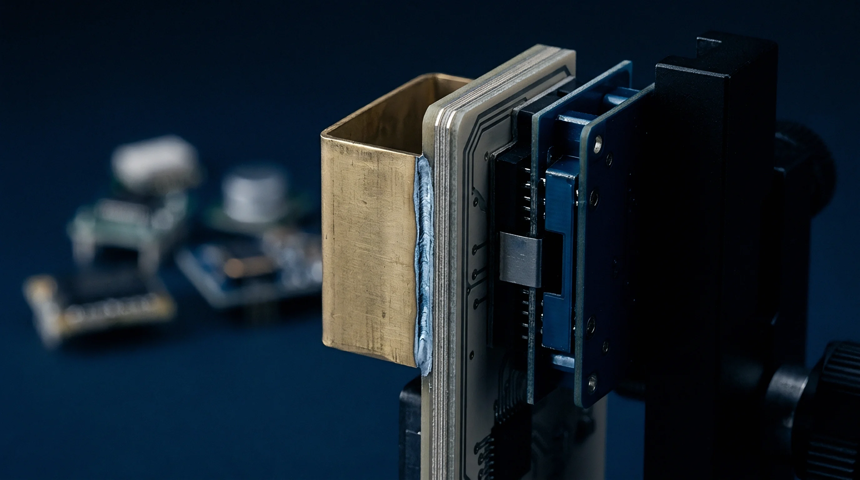
Validating crystal-less cellular hardware requires environmental stress screening that goes well beyond traditional crystal test routines. A standard verification setup measures frequency error under steady-state conditions inside an RF isolation box at room temperature. For crystal-less architectures, steady-state testing misses the core failure mode entirely.
The test bench must measure dynamic thermal transients while the radio transitions between extreme power states inside an environmental chamber, driving continuous maximum-power transmissions across rapid temperature ramps.

Bench Instrumentation and Transient Analysis
Assessing open-loop frequency deviation requires synchronized high-speed RF capture instrumentation. The following sequence details the verification methodology implemented on the radio test bench:
- Mount the device under test inside an environmental chamber over an RF test fixture, connecting high-bandwidth coaxial cabling to an automated communication tester.
- Attach calibrated micro-thermocouple probes directly to the radio module shielding directly over the power amplifier and local oscillator regions.
- Stabilize the environmental chamber temperature at negative forty degrees Celsius for sixty minutes to saturate all internal components.
- Command the communication tester to establish a narrowband IoT signaling connection, configuring maximum repetition settings on the physical uplink shared channel at twenty-three decibels relative to one milliwatt.
- Capture the raw in-phase and quadrature transmission bursts using a vector signal analyzer synchronized to the communication tester trigger bus.
- Execute windowed short-time Fourier transforms across the captured burst to extract instantaneous carrier frequency error as a function of burst elapsed time.
- Ramp the environmental chamber temperature at two degrees Celsius per minute toward positive eighty-five degrees Celsius while repeating continuous burst acquisitions.
The instrumentation must isolate momentary phase noise from sustained thermal drift. Thermal transients produce continuous, unidirectional carrier drift, whereas local oscillator phase jitter shows up as symmetrical sideband widening. Vector signal analyzers with deep capture memory trace the full burst sequence, resolving frequency shifts down to sub-Hertz increments over windows up to two thousand milliseconds.
Powering the module from a low-noise linear supply with recovery times under ten microseconds keeps battery sag from confounding the thermal drift data.
Could Base Station Algorithms Compensate Unlocked Uplink Chirp?
Base station manufacturers write proprietary equalization routines into their uplink signal processing software to improve receiver sensitivity. Some high-tier base station receivers run joint channel and frequency offset tracking capable of following gradual phase shifts across long physical resource blocks. This tracking relies on regular demodulation reference symbols placed throughout the uplink frame.
If the carrier drifts non-linearly between those reference points, the channel filter interpolates the trajectory incorrectly. Because 3GPP specifications do not dictate internal base station equalizer designs, real-world receiver performance against crystal-less chirp varies widely between infrastructure vendors.
Carrier acceptance testing remains the decisive hurdle. Network operators across North America and Western Europe enforce strict frequency stability standards during drive tests through rail corridors and inside deep building basements. A module can sail through static bench tests at twenty-five degrees Celsius yet fail field certification under sudden solar heating inside an outdoor utility enclosure.
Conservative development budgets allocate fifty thousand dollars for potential laboratory re-testing cycles.
Whether base station vendors will adjust their receiver equalization firmware to accommodate wider carrier drift from low-cost IoT nodes remains an open commercial question.
Reckoning
Choosing a crystal-less radio architecture involves balancing immediate component savings against lifetime maintenance and operating costs. Removing a twenty-six megahertz or thirty-eight point four megahertz temperature-compensated crystal oscillator cuts roughly twenty-five to forty-five cents from the raw bill of materials. It also recovers around six square millimeters of board space, eliminating traces that could otherwise pick up noise from switching power supplies.
In miniature tracking tags or single-use medical sensors, that board area reduction provides clear packaging benefits.
Those upfront hardware savings must be weighed against battery life and field certification risks. When an unreferenced transceiver drifts under load, base station packet error rates climb at the cell edge. A node operating with one hundred fifty decibels of path loss might close its link reliably using four repetitions when backed by an external crystal.
That same device without a crystal reference suffers subcarrier phase errors, fails cyclic redundancy checks, and forces the network protocol to step up to sixty-four or one hundred twenty-eight repetitions, scaling transmit airtime thirty-fold and doubling battery consumption.
A twelve hundred milliamp-hour lithium thionyl chloride primary cell provides a nominal ten-year operating life at two transmissions per day. Stretching transmit durations from twenty milliseconds to six hundred milliseconds per message exhausts that cell in under eighteen months. Saving thirty cents on a quartz crystal can trigger a truck roll costing one hundred fifty dollars per unit to replace prematurely drained batteries in utility meters.
Spectrum band selection compounds the issue. Devices operating in lower sub-gigahertz allocations, including European Band 20 or North American Band 12, run in tight channel rasters where thermal drift easily pushes sidebands past out-of-band emission boundaries. Higher frequency bands face a different problem: because absolute Hertz shift scales directly with carrier frequency, a zero point one part per million drift produces twice the absolute frequency displacement at eighteen hundred megahertz that it does at nine hundred megahertz.
Evaluating crystal-less cellular designs requires looking past initial bill-of-materials costs. For battery-powered nodes operating indoors under strong coverage with short bursts, crystal-less designs deliver genuine savings. For utility meters, infrastructure monitors, or asset trackers exposed to weather extremes and weak signal margins, retaining the external crystal oscillator is the safer choice.
Front-end component savings disappear the moment unexpected field retransmissions force an early battery replacement.