Cellular Internet of Things Power Budget Management Principles
Cellular IoT power management matches PSM and eDRX timers to application frequency while decoupling peak pulse currents from battery internal resistance.


Floor
Low power cellular modes allow IoT devices to achieve long operating lives on primary batteries. Cellular chipsets designed for LTE-M and NB-IoT incorporate specialized operational states that drastically reduce power consumption during periods of radio inactivity. In traditional cellular designs, receivers continuously poll base stations to maintain synchronized paging slots, resulting in active sleep currents between 1.5 milliamperes and 3.0 milliamperes.
Modern low power wide area standards break this baseline by introducing extended idle states that drop static drain into the sub-microampere range, directly extending battery lifespan.

Energy Mechanics of Low Power Cellular Modes
Modern cellular modems transition through distinct internal states that dictate current consumption. When a device completes a data transmission, it enters the Radio Resource Control Connected state until the base station issues a release order or the inactivity timer expires. During this active tail period, the modem draws between 40 milliamperes and 80 milliamperes while listening for downstream control channels.
Once released, the modem enters Radio Resource Control Idle state, where extended Discontinuous Reception allows the receiver to turn off for negotiated intervals ranging from 5.12 seconds to 40.96 seconds in LTE-M, or up to 1048.57 seconds in NB-IoT, though sleep floor currents degrade over higher temperatures.
Power Saving Mode achieves the lowest continuous energy baseline by allowing the modem to unregister its radio circuits completely while maintaining its core network registration context. In this state, the module switch-mode power regulators enter ultra-low leakage operation, and internal clocking drops to low frequency crystal oscillators operating at 32.768 kilohertz. Static current draw during Power Saving Mode ranges from 800 nanoamperes to 3.0 microamperes depending on operating voltage, silicon architecture, and ambient thermal conditions.
Because the module retains its Subscriber Identity Module security context and network IP address allocation, re-awakening from Power Saving Mode bypasses full Evolved Packet System attach procedures, reducing the energy cost of subsequent transmissions.
Sleep state floor currents determine battery longevity during extended field operation when data transmissions occur infrequently.
| Operating State | LTE-M Current Range | NB-IoT Current Range | Receiver State | Primary Energy Driver |
|---|---|---|---|---|
| Power Saving Mode | 800 nA to 2.5 µA | 800 nA to 2.0 µA | Disabled | Silicon leakage and real-time clock retention |
| Extended Discontinuous Reception Idle | 15 µA to 35 µA | 10 µA to 25 µA | Pulsed periodic listen | Paging Time Window duration and cycle span |
| Radio Resource Control Connected Idle | 1.2 mA to 2.8 mA | 1.0 mA to 2.2 mA | Continuous listen | Base station paging channel polling interval |
| Active Receiver Window | 35 mA to 55 mA | 28 mA to 45 mA | Active RF front end | Low noise amplifier and baseband processing |
| Active Transmitter Peak (+23 dBm) | 310 mA to 490 mA | 220 mA to 340 mA | Disabled | Power amplifier efficiency and load impedance |

Power Saving Mode Timer Architecture
Deep sleep states rely on two governing timers negotiated with cellular infrastructure during registration. The T3412 extended periodic Tracking Area Update timer defines the maximum period between mandatory status messages sent from the device to the mobility management entity. The network allows requested T3412 values up to 413 days, though operational deployments commonly select values between 12 hours and 24 hours to balance location accuracy with idle efficiency.
The T3324 active timer specifies the duration the device remains in extended Discontinuous Reception Idle mode after completing a radio transaction before descending into Power Saving Mode.
Configuring T3324 involves direct compromises between downlink latency and total milliampere-hour expenditure. A long active timer keeps the radio receiver available for incoming server commands without forcing a complete wake-up sequence, consuming significant background energy during the window. A zero-second active timer forces the module into deep sleep immediately after receive frame processing, shutting off downstream reachability until the next sensor-driven or periodic wake cycle.
Selecting T3412 values higher than the sensor measurement cycle ensures that radio registration overhead remains lower than total application energy consumption.


Spike
Radio frequency transmission introduces severe current demands that strain primary cell power sources. While sleep state management controls background energy drain, active transmission pulses establish the peak current requirements that dictate power supply hardware architecture. Cellular power amplifiers operating at high output power demand significant instantaneous current bursts, triggering voltage drops across power source internal impedances ~ a problem worsened when passivation increases internal cell resistance.
If terminal voltage collapses below module reset limits during a transmission pulse, hardware brownout conditions occur and terminate communication cycles mid-frame, though supercapacitors can be added to buffer these high pulse currents.

Transient Current Demands during Radio Frequency Bursts
Cellular transmitters operate in pulsed bursts that draw hundreds of milliamperes from the power supply. In LTE-M and NB-IoT architectures, maximum transmit powers reach +23 dBm or +20 dBm depending on module power class ratings. At +23 dBm output power into a 50-ohm load, power amplifier efficiency ranges between 35 percent and 45 percent, requiring the primary supply rail to furnish active currents up to 500 milliamperes.
These high current pulses occur on millisecond timescales, corresponding to subframe burst structures mandated by physical layer transport protocols.
When battery internal direct current resistance is high, current surges generate instantaneous line drops according to basic resistive drop principles. Primary battery chemistries like lithium thionyl chloride exhibit intrinsic internal resistance values between 10 ohms and 40 ohms in unpassivated or aged conditions. A 500-milliampere load pulse applied across a 20-ohm internal cell resistance causes an immediate 10-volt internal drop, collapsing supply voltage below the typical 3.0-volt operational threshold of cellular modems.
This voltage collapse forces supply rail decoupling design to mitigate severe transient drops.
Drawing a 500-milliamp pulse across a 10-ohm internal battery resistance causes a instantaneous terminal voltage drop of 5 volts.

Supply Impedance and Voltage Dip Mitigations
High internal resistance within primary batteries creates operational challenges during high power radio events. Hardware engineers implement localized storage systems to isolate primary batteries from peak radio transmit current spikes. Hybrid layer capacitors connected in parallel with primary lithium cells offer high capacitance density alongside low equivalent series resistance below 100 milliohms.
During active power amplifier bursts, the low impedance hybrid capacitor provides the instantaneous pulse current, preserving primary cell terminal voltage while allowing the primary battery to recharge the capacitor slowly during low current sleep intervals.
Decoupling hardware designs incorporate structured power loss mechanisms when peak transient requirements receive insufficient isolation:
- Passivation Layer Drop occurs when stored lithium cells develop a high resistance passivation film that collapses initial supply voltage under load pulses until electrochemical activation clears the layer.
- Brownout Reset Trip occurs when primary supply rails drop below modem integrated circuit reset comparator limits, triggering ungraceful baseband restarts and corrupting non-volatile state memory.
- Thermal Ohmic Loss occurs when high current surges generate resistive heat inside high impedance cells, dissipating usable chemical energy as non-recoverable thermal energy.
- Electrolyte Polarization Strain occurs when continuous high pulse currents create localized ion depletion zones inside primary batteries, reducing effective output voltage during extended transmit bursts.
Neglecting peak pulse impedance forces hardware resets during cold weather, truncating module operational life before ten percent of nominal milliamp-hour capacity leaves the cell.


Margin
Operating at the limits of radio sensitivity alters module power profiles significantly. Cellular IoT standards achieve extended coverage into basements and subterranean utility vaults by applying repetition techniques that improve signal-to-noise ratios at the receiver. While these coverage enhancement mechanisms maintain connectivity over extreme path loss distances, repeating subframes and running at maximum output power multiplies transmit duration and accelerates battery capacity loss, transforming what would be a sub-second transaction into an extended multi-second power event.

Link Budget Penalties in Coverage Enhancement
Cellular standards incorporate repetition techniques to reach modems located deep indoors or underground. Standard LTE links maintain maximum coupling loss figures around 144 decibels. LTE-M expands link budgets to 155.7 decibels, whereas NB-IoT reaches up to 164 decibels of maximum coupling loss.
To bridge these extreme attenuation gaps, physical channel subframes repeat multiple times across consecutive radio frame slots, allowing receiving base stations to accumulate physical layer energy through joint coherent processing.
Under good propagation conditions in Coverage Enhancement Mode A, an LTE-M modem transmits data payloads using single subframes or low repetition counts between 1 and 4 repetitions. When operating in deep shadow or underground pits requiring Coverage Enhancement Mode B, subframe repetitions scale up to 32, 64, or 128 times for LTE-M, and up to 2048 times in NB-IoT. This airtime scaling increases cumulative energy consumption per transmitted byte, as the power amplifier remains active across hundreds of consecutive subframes instead of turning off after milliseconds.
Clause 5.1 of 3GPP Technical Specification 36.211 permits subframe repetitions up to 2048 times, which scales total radio transmission energy exponentially.
| Coverage Level | Max Coupling Loss | Subframe Repetitions | Airtime Duration | Relative Transmit Energy |
|---|---|---|---|---|
| Normal Coverage (CE Mode A) | 144.0 dB | 1 Repetition | 10 ms to 40 ms | 1.0x (Baseline) |
| Extended Coverage (CE Mode A) | 149.0 dB | 4 Repetitions | 40 ms to 160 ms | 3.8x to 4.2x Baseline |
| Deep Coverage (CE Mode B) | 155.7 dB | 32 Repetitions | 320 ms to 1.28 s | 30.5x to 33.0x Baseline |
| Extreme Coverage (NB-IoT Rel 13) | 164.0 dB | 128 Repetitions | 1.28 s to 5.12 s | 120.0x to 135.0x Baseline |

Repetition Multipliers and Airtime Scaling
Base stations instruct modules to retransmit individual subframes multiple times when path loss is high. Closed loop power control algorithms in cellular infrastructure force modems operating under high path loss to set output powers to maximum levels, typically +23 dBm. Combining maximum transmit power with expanded subframe repetition counts creates extreme battery drain conditions.
The airtime multiplier directly scales the electrical charge spent per telemetry payload, meaning a device that operates for ten years in direct line-of-sight conditions might exhaust its primary battery within two years if relocated inside a metallic containment shield.
Transmitter energy budgets expand when random access preamble channels experience repetition scaling during network registration. Before data transfer begins, the modem transmits physical random access channel preambles to establish temporal synchronization with the carrier cell tower. If the base station misses initial preambles due to heavy path attenuation, the modem ramps output power and increases preamble repetition factors, spending substantial battery capacity before application layer transport layer handshakes commence.
Silicon vendors frequently state that maximum coverage enhancement modes maintain link connectivity while failing to note that continuous transmission at maximum repetitions depletes a lithium battery in under six months.


Interval
Transmission frequency directly scales overall current draw across product deployment lifespans. Power budget modeling relies on calculating duty cycle ratios between sleep floor durations and active communication events, both of which are heavily influenced by carrier active connection timers and whether unacknowledged datagrams are used to shorten active tail durations. Because transitioning from deep sleep to connected states incurs fixed protocol synchronization overhead, aggregating multiple sensor readings into periodic batch updates consumes significantly less cumulative energy than transmitting individual measurements immediately upon generation.

Which Operational Parameters Govern Cellular Keep Alive Overhead?
Maintaining active carrier registration requires periodic background communications between the modem and base station. Even when application telemetry remains static, protocol state maintenance requires periodic Tracking Area Updates and domain name resolution queries. Selecting application transport layer protocols influences how frequently modems must transmit keep-alive packets to navigate carrier infrastructure network address translation timeouts.
UDP connections typically require keep-alive packets every 15 minutes to 30 minutes to maintain open pinholes, whereas Non-IP Data Delivery via Service Capability Exposure Function eliminates transport layer keep-alive requirements entirely.
RRC Inactivity Timers established by carrier infrastructure determine how long modems remain in high power connected states after data transmission ceases. Base stations enforce inactivity timer durations between 5 seconds and 20 seconds. During this window, the receiver listens continuously for additional downstream packets, consuming active connected currents around 50 milliamperes.
If application designs generate frequent small messages spaced slightly wider than the inactivity timer duration, the modem spends the majority of its operational life locked in active connected states, rapidly exhausting battery reserves.
System designers follow specific configuration guidelines to align transmission timing with energy goals:
- Configure the module to request specific T3412 and T3324 timer values during initial attach.
- Select unacknowledged transport layer protocols to eliminate bidirectional handshake overhead.
- Align sensor measurement sampling periods with configured extended reception cycles.
- Set application data payload sizes below maximum segment boundaries to avoid packet fragmentation.
- Disable unnecessary network management reports and active location polling functions.
Executing these parameter configurations minimizes protocol overhead during periodic wake sequences.
Transmitting small telemetry payloads inside unacknowledged UDP datagrams bypasses connection setup energy overheads and reduces active tail duration.

Non IP Data Delivery versus User Datagram Protocol
Standard internet protocol overhead adds substantial bit count to small sensor measurements. User Datagram Protocol packets include 20 bytes of IP header and 8 bytes of UDP header information, whereas Transmission Control Protocol headers add 20 to 60 bytes per packet alongside bidirectional acknowledgement exchanges. For a 10-byte sensor payload, standard transport encapsulation increases data size by 300 percent, directly extending RF output burst durations and power amplifier activation energy.
Non-IP Data Delivery bypasses IP header stacks entirely by routing raw payload bytes directly through cellular control plane signalling pathways to service capability exposure platforms. Eliminating IP overhead reduces required physical layer subframe counts, allowing shorter transmission airtimes. Control plane data transfers allow devices to transmit small payloads directly within Extended Session Management signaling messages during Tracking Area Updates, avoiding the complete Radio Resource Control connection establishment state machine.
Adherence to ETSI TS 124 301 clause 9.9.3.4A forces the modem to clear active timers during cell reselection, preventing unexpected energy drain during carrier grid switching.


Chemistry
Selecting an appropriate primary energy storage medium dictates physical cell behavior under load. Battery chemical formulations deliver distinct trade-offs between self-discharge rates, energy density, active pulse capability, and thermal performance range. Because lithium chemistry governs low-temperature behavior and cell degradation scales directly with operating temperature, cold conditions can severely drop available capacity.
Deploying cellular modems without matching battery output impedance profiles to transmission pulse current requirements results in premature power failure long before chemical energy depletion occurs.

Battery Selection Criteria for High Peak IoT Systems
Primary lithium cells exhibit distinct discharge characteristics that determine suitability for cellular transmitters. Lithium Thionyl Chloride (LiSOCl2) delivers high nominal cell voltage of 3.6 volts and impressive energy density exceeding 400 watt-hours per kilogram, alongside an exceptionally low self-discharge rate below 1 percent per year at room temperature. However, LiSOCl2 cells develop passivating film layers during storage that increase cell internal resistance, causing sharp initial voltage dips under current load pulses.
Lithium Manganese Dioxide (LiMnO2) operating at 3.0 volts offers higher instantaneous pulse rate capability and lower passivation susceptibility than LiSOCl2, making it attractive for high pulse application loads. However, LiMnO2 cells demonstrate higher self-discharge rates between 1.5 percent and 2.5 percent per year, limiting deployment lifespans in multi-decade utility applications. Combining primary LiSOCl2 cells with parallel Hybrid Layer Capacitors combines ultra-low self-discharge storage characteristics with high peak pulse current delivery capabilities required by cellular transmitters.
| Chemistry Type | Nominal Voltage | Self-Discharge Rate | Passivation Severity | Continuous Pulse Capability |
|---|---|---|---|---|
| Lithium Thionyl Chloride (LiSOCl2) | 3.6 V | 0.8% to 1.2% / year | High (Requires HLC) | Low (50 mA to 100 mA max) |
| Lithium Manganese Dioxide (LiMnO2) | 3.0 V | 1.5% to 2.5% / year | Low to Moderate | High (500 mA to 1000 mA) |
| Lithium Iron Phosphate (LiFePO4) | 3.2 V | 2.0% to 5.0% / month | None (Rechargeable) | Very High (2000 mA+) |
| Hybrid Layer Capacitor (HLC) | 3.6 V to 3.9 V | Negligible Leakage | None | Extreme (1000 mA to 3000 mA) |

Self Discharge Dynamics and Depletion Thresholds
Internal chemical degradation reduces available energy over prolonged deployment durations regardless of radio usage. Self-discharge processes accelerate exponentially with ambient operating temperatures according to standard Arrhenius thermal rate equations. Operating a primary lithium cell continuously at +60 degrees Celsius doubles its annual self-discharge rate, converting usable battery capacity into background thermal leakage.
Thermal derating calculations must account for localized temperature elevation within sealed industrial enclosures.
When selecting low voltage cutoff thresholds inside power management integrated circuits, hardware designers evaluate cell discharge curves under load. As primary cells near total discharge, internal resistance rises sharply while nominal terminal voltage decays. Setting module power management shutdown thresholds too high causes the system to terminate operation while substantial capacity remains in the cell; setting thresholds too low risks baseband memory corruption when load pulses trigger unexpected voltage brownouts.
Engineers evaluate several core design attributes when qualifying battery energy storage hardware:
- Pulse Depassivation Schedule defines periodic background transmission routines implemented to burn off accumulated cell passivation film layers without triggering supply brownouts.
- Low Temperature Derating Model calculates nominal capacity loss factors applied across sub-zero operating environments where electrolyte viscosity increases internal impedance.
- Transient Voltage Margin Threshold specifies minimum allowable supply voltage margins maintained above modem brownout trip points during maximum power amplifier pulses.
- Equivalent Series Resistance Limits establishes maximum allowable combined primary cell and decoupling capacitor internal resistance values across full service lifespans.
Field deployment teams continue to debate whether active pulse depassivation routines consume more cumulative energy over ten years than the physical voltage dips they prevent.


Audit
Empirical validation of power consumption profiles prevents premature battery exhaustion in deployed hardware. Mathematical models based on static datasheet numbers consistently underestimate continuous real-world energy drain by ignoring dynamic network variables like base station handshakes, protocol retransmissions, coverage enhancement repetitions, and signal acquisition search phases. Because field conditions can drastically alter operational lifespan, accurate energy accounting requires strict pulse logging across a high dynamic range.
Rigorous verification workflows rely on physical bench profiling under simulated carrier grid conditions to confirm total microampere-hour consumption profiles before volume production sign-off.
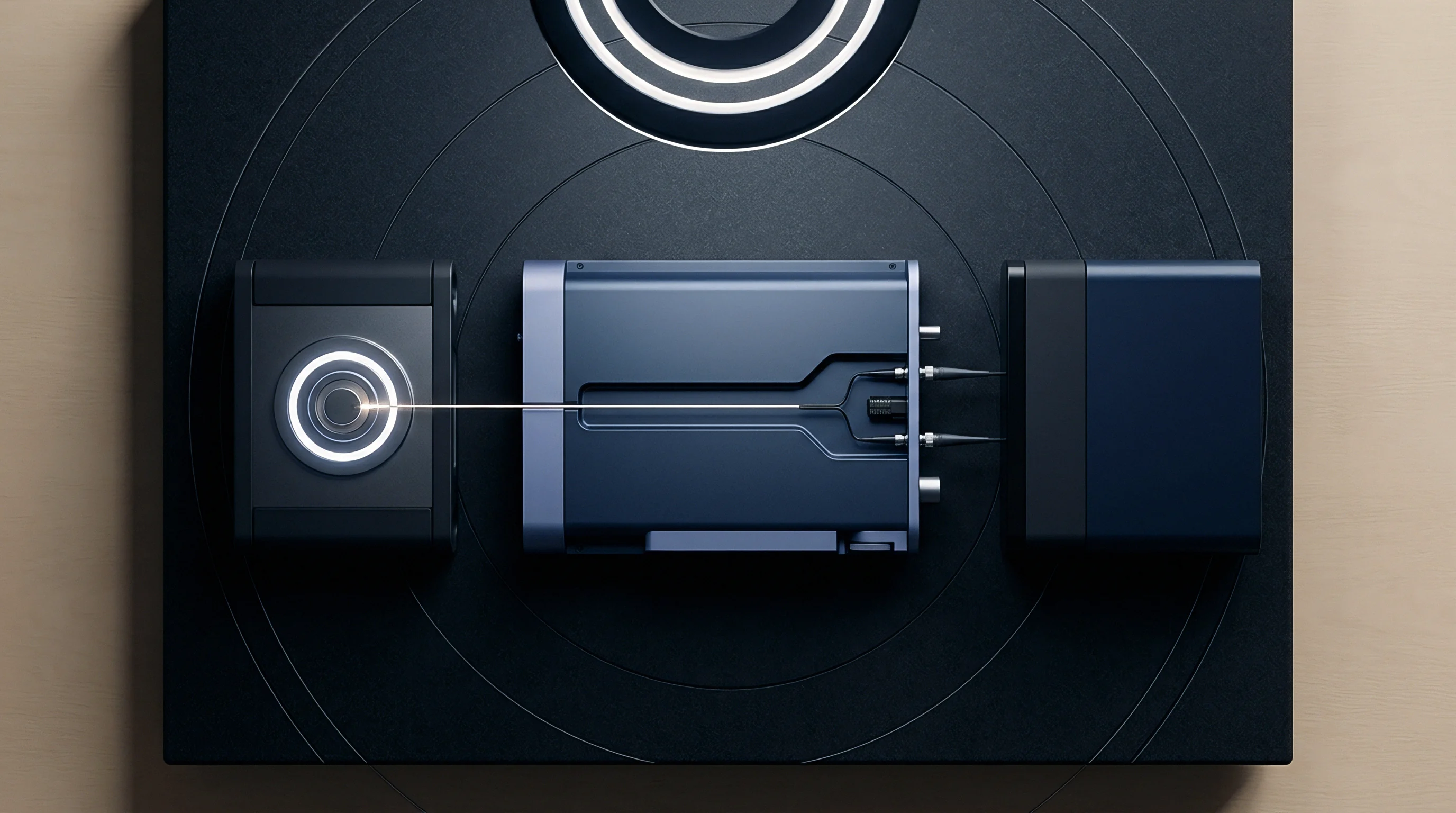
Bench Profiling and Current Measurement Workflows
Accurate current logging requires hardware equipment capable of capturing broad dynamic ranges simultaneously. Cellular IoT devices transition rapidly across five orders of magnitude in current consumption, shifting from 800 nanoamperes in Power Saving Mode sleep to 500 milliamperes during active transmit bursts within microseconds. Standard digital multimeters lack sufficient bandwidth and dynamic autoranging speed to measure these fast current transients, resulting in severe measurement integration errors.
High-speed power profiling analyzers utilize continuous high frequency sampling architectures operating at 100 kilohertz or higher, paired with auto-ranging shunt resistor banks. These power analyzers record instantaneous current draw alongside supply voltage lines, calculating cumulative integrated charge in coulombs across full active transmission cycles. Connecting the unit under test to dedicated cellular communication testers allows engineers to control signal attenuation, coverage enhancement repetition profiles, and carrier timer parameters during benchmark logging sessions.

Verification Procedure for Energy Budget Conformance
Systematic energy calculations convert measured current traces into realistic battery lifespan projections. Consider a worked mathematical service model for an industrial telemetry monitor operating on a primary LiSOCl2 cell rated at 2400 milliampere-hours (8640 coulombs) nominal capacity, with an assumed 10 percent safety derating for self-discharge and thermal degradation, leaving 2160 milliampere-hours of usable capacity.
Assume the device wakes once every 12 hours (2 cycles per day) to transmit a 100-byte sensor payload over LTE-M. Bench measurement logs show the operational current profile breaks down into four sequential stages per wake cycle:
First, the initial wake and cell search phase draws an average current of 35 milliamperes for 1.2 seconds, consuming 0.0117 milliampere-hours. Second, the active transmission phase in CE Mode A (2 repetitions at +18 dBm transmit power) draws an average current of 180 milliamperes for 0.8 seconds, consuming 0.0400 milliampere-hours. Third, the active RRC connected tail phase governed by carrier settings draws an average current of 45 milliamperes for 6.0 seconds while waiting for network release, consuming 0.0750 milliampere-hours.
Fourth, the extended Discontinuous Reception idle phase dictated by the T3324 active timer draws an average current of 2.0 milliamperes for 10.0 seconds before entering deep sleep, consuming 0.0056 milliampere-hours.
Summing these four phases yields a total active energy expenditure of 0.1323 milliampere-hours per wake transaction. Across two daily wake cycles, active energy draw equals 0.2646 milliampere-hours per day. Between active cycles, the device spends approximately 23.99 hours in Power Saving Mode deep sleep, drawing a continuous floor current of 1.5 microamperes, which consumes 0.0360 milliampere-hours per day.
Combining active and sleep consumption yields a total daily drain of 0.3006 milliampere-hours per day. Dividing the usable 2160 milliampere-hour cell capacity by total daily drain establishes a calculated operational lifespan of 7185 days, or approximately 19.6 years under nominal room temperature conditions.
Calculating average daily microampere-hour consumption across seasonality shifts yields an operational energy figure that prevents premature field failure in remote utility installations.