Impact of Temperature Induced Dielectric Permittivity Variations on Automotive Radar Beam Distortion
Temperature variations alter substrate dielectric constant at 77 GHz, causing phase velocity shifts, mainlobe beam squint, and spatial target dislocations.


Heat
Dielectric behavior inside automotive radar sensor assemblies shifts continuously during routine driving. Substrates supporting 76 to 81 GHz microstrip antenna arrays experience relative permittivity drift under direct sunlight, under-hood heat, and power dissipation from transmitter monolithic microwave integrated circuits. Real relative permittivity shifts alter phase velocity along transmission lines, while loss tangent variations change attenuation and radiation efficiency.
Modules rated for the ISO 16750-4 code S temperature range operate between negative 40 degrees Celsius and 125 degrees Celsius ~ a 165-degree envelope that drives significant electromagnetic and structural changes in both substrates and radome enclosures.
How high-frequency circuit board laminates respond to heat depends heavily on chemical composition and reinforcement. PTFE-based laminates filled with micro-dispersed ceramic particles exhibit a negative temperature coefficient of dielectric constant, causing relative permittivity to drop as temperatures rise. Hydrocarbon ceramic composites and thermoset resins behave oppositely, gaining relative permittivity as thermal energy increases molecular dipole mobility.
The magnitude of this drift ~ measured by the temperature coefficient of dielectric constant in parts per million per degree Celsius ~ determines the operational stability of the millimeter-wave antenna layout.
| Material Classification | Base Polymer / Filler | Nominal Permittivity at 77 GHz | Loss Tangent at 77 GHz | Thermal Coefficient of Permittivity (ppm/°C) | Coefficient of Thermal Expansion (ppm/°C) |
|---|---|---|---|---|---|
| Woven Glass PTFE | PTFE / Micro-glass fiber | 3.00 | 0.0013 | -160 to -180 | 12 (X/Y axis) |
| Ceramic PTFE Composite | PTFE / High-dielectric ceramic | 3.00 | 0.0010 | -3 to -12 | 8 to 11 (X/Y axis) |
| Thermoset Hydrocarbon | Cross-linked Hydrocarbon / Ceramic | 3.48 | 0.0037 | +35 to +50 | 14 to 17 (X/Y axis) |
| Polybutylene Terephthalate | PBT with 30 percent Glass Fiber | 2.82 | 0.0085 | +120 to +160 | 25 to 35 (Isotropic) |
| Polycarbonate | Unfilled PC Resin | 2.75 | 0.0060 | +90 to +130 | 60 to 70 (Isotropic) |
| Polyetherimide | Unfilled PEI Resin | 2.98 | 0.0025 | +60 to +85 | 45 to 55 (Isotropic) |
Radome material selection introduces another source of electromagnetic distortion. Plastic front covers made from polybutylene terephthalate, polycarbonate, or polyetherimide sit directly in the array’s radiation path, serving primarily to shield electronics from stone impacts, wash-down fluids, and moisture. At 77 GHz, where free-space wavelength is roughly 3.9 millimeters, typical half-wavelength wall thicknesses of 1.1 to 1.3 millimeters become sensitive to dielectric variations.
As thermal swings shift the polymer housing’s real permittivity, half-wave resonance degrades, creating internal reflections and parasitic insertion losses back into the transmit elements.
Thermal expansion compounds permittivity shifts by altering physical geometry. When a microstrip line expands, trace length increases while substrate thickness decreases slightly under Z-axis strain. This pulls the resonant frequency of patch elements lower, compounding the phase shift created by permittivity drift.
In radomes, volumetric expansion alters wall thickness and pushes transmission passbands away from the 76 to 81 GHz band.
Relative permittivity reductions in PTFE laminates accelerate phase propagation speed at elevated operating temperatures.
Substrate and radome loss tangents both increase with temperature. Higher dissipation lowers radiated power from patch elements and degrades the Q-factor of planar filters. This converted RF energy creates localized dielectric heating, triggering thermal feedback loops inside sealed housings.
At 105 degrees Celsius ambient, dielectric attenuation through a standard 50-ohm microstrip feed network can rise up to 30 percent above room-temperature baselines, directly reducing signal-to-noise ratio and maximum detection range.
Thermal cycling introduces structural hysteresis into composite laminates over time. Repeatedly swinging between cold soak states and high operating temperatures relaxes polymer chains and forms micro-fissures at the boundary between glass fiber bundles and resin. This structural degradation causes permanent shifts in baseline relative permittivity, leading to long-term calibration drift in safety sensors.
Radar systems depend on predictable material properties to synthesize clean beams across all weather conditions. Left unchecked, material variations degrade target tracking accuracy during thermal transients.
- Resin Retraction Drift occurs when polymer matrices expand unevenly away from glass reinforcement fibers during thermal cycling, creating localized permittivity drops across feed networks.
- Resonance Detuning Failure occurs when permittivity variations shift the antenna operational band off the 77 GHz carrier frequency, driving reflection coefficients above acceptable matching limits.
- Attenuation Gradient Failure develops when non-uniform temperatures across the board cause localized RF absorption, unbalancing amplitude weights across the array.
- Passband Phase Distortion occurs when thermal permittivity shifts skew the electrical length of bandpass filters, introducing unexpected group delay ripple into radar chirps.
Software algorithms can recalibrate beamforming networks on the fly to absorb dielectric shifts during operation, preserving baseline radar performance.


Phase
Signal propagation along planar feed structures depends directly on the effective dielectric constant of the microstrip or substrate integrated waveguide. Phase velocity equals the speed of light divided by the square root of that effective dielectric constant. As thermal shifts alter permittivity, phase velocity changes across every millimeter of trace length.
Series-fed patch arrays common in automotive FMCW radar depend on precise electrical spacing between elements to form accurate phase relationships and radiation patterns.
Phase distribution across an array determines how waves combine vectorially in the far field. In a linear series-fed array with N radiating elements, thermal changes in effective dielectric constant accumulate along the feed line. Element one, nearest the transmit MMIC, receives the nominal phase, while downstream elements build up phase errors proportional to their distance along the trace.
Total phase error at the final element equals feed length multiplied by the shift in the phase propagation constant.
Corporate feed networks handle thermal phase distortion differently than series-fed architectures. Symmetric corporate feeds route energy through identical path lengths to each element, maintaining uniform phase shifts when the board heats evenly. While this uniform shift preserves beam direction, it still alters overall input impedance and phase center position.
Thermal gradients across the circuit board disrupt this balance, creating asymmetric phase errors that distort radiation patterns.

Transmission Line Velocity Variations and Array Phase Skew
Electrical path length directly dictates beamforming accuracy in planar arrays. On a hydrocarbon ceramic substrate, rising temperatures increase effective permittivity and slow wave propagation. This added electrical length introduces progressive phase lag at each subsequent element.
Phase shift per unit length equals two pi times operating frequency divided by free-space light speed, multiplied by the change in the square root of effective permittivity.
At 77 GHz, a wavelength in standard high-frequency dielectrics measures roughly 2.1 millimeters. A physical trace shift or permittivity change altering electrical path length by just 0.1 millimeter induces over 17 degrees of phase error. In phased arrays using digital beamforming or fixed delays, channel errors exceeding 5 degrees degrade spatial resolution, raise sidelobes, and wash out the deep nulls required by angle-of-arrival algorithms.
ETSI EN 302 264 sets strict masks for automotive radar radiation patterns across all operating temperature ranges.
Differential phase shifts between transmit and receive channels degrade both monopulse and digital beamforming performance. Modern automotive radars combine multiple TX and RX channels to form virtual synthetic apertures. When transmit arrays sit adjacent to power-dissipating MMICs while receive arrays lie near cooler outer housing walls, steep thermal gradients form across the board.
Transmit channels then experience different phase velocity shifts than receive channels, corrupting the covariance matrices used in MUSIC or ESPRIT direction-of-arrival algorithms.

When Does Thermal Phase Skew Trigger Target Ghosting?
Target ghosting occurs when thermal phase corruption pushes array sidelobes above the detection thresholds of constant false alarm rate processors. When phase errors across virtual channels exceed 15 degrees RMS, far-field patterns show elevated sidelobes relative to the main beam. Signal processors interpret these sidelobes as real reflections, placing phantom targets alongside actual road obstacles.
Phase distortion also degrades the deep pattern nulls required to suppress multipath reflections from road surfaces and guardrails. Reduced null depth allows environmental clutter to inject phase noise into receive channels, obscuring low-RCS targets like pedestrians or cyclists. Preserving channel-to-channel phase alignment is essential for resolving close targets in dense traffic.
Phase stability in millimeter-wave arrays follows a direct relationship: phase drift scales linearly with channel length and the substrate’s thermal dielectric coefficient.


Refraction
Electromagnetic radiation passing through a radome bends whenever local refractive index varies across its surface. Assuming relative permeability equals unity, the refractive index is simply the square root of relative permittivity. Direct sunlight on one side of a bumper combined with internal heat from operating electronics creates temperature gradients across the plastic cover, turning what was a uniform dielectric sheet into a spatially graded lens.
Wavefront distortion at the radome interface shifts the propagation angle of emitted energy. By Snell’s Law, energy transitioning from a region of higher refractive index to lower bends away from the surface normal. When radome permittivity varies across the aperture, different sections of the wavefront exit with unequal phase delays, tilting the composite wave surface in the far field.
Mainlobe squint angle represents the primary geometric error driven by asymmetric thermal refraction. The radar beam’s electrical boresight rotates away from its mechanical axis toward regions of lower permittivity. In a long-range forward-looking radar tracking targets at 200 meters, a beam squint of just 0.5 degrees shifts the beam center laterally by 1.75 meters ~ sufficient to misassign tracking to adjacent highway lanes.

Snellian Deviation across Thermal Radome Gradients
Lateral thermal gradients across the radome alter local optical path lengths, defined as physical thickness multiplied by refractive index. As localized hotspots form, temperature-induced polarizability changes increase the refractive index of standard engineering polymers, extending the optical path. Energy passing through warmer regions exits with delayed phase relative to cooler areas, distorting wavefront curvature.
Phase curvature across the aperture broadens the main beam and degrades peak boresight gain. Beam broadening reduces spatial resolution, making it difficult to separate closely spaced vehicles at range. Concurrently, lower gain at the beam center drops return signal SNR, shortening maximum range during high-temperature driving.

Bore Sight Errors and Spatial Target Dislocation
Boresight error is the angular discrepancy between a target’s true position and its calculated location. This dislocation impairs driver assistance systems like adaptive cruise control and automated emergency braking. Boresight offsets shift dynamically as vehicle speed, external airflow, and internal component temperatures change.
| Temperature Differential Across Radome (°C) | Local Permittivity Shift (PEI Resin) | Boresight Angle Shift (Degrees) | Peak Gain Loss (dB) | Mainlobe Beamwidth Broadening (%) | Lateral Dislocation at 150m Range (m) |
|---|---|---|---|---|---|
| 5 | +0.0012 | 0.04 | 0.10 | 0.8 | 0.10 |
| 15 | +0.0036 | 0.12 | 0.28 | 2.4 | 0.31 |
| 30 | +0.0072 | 0.26 | 0.65 | 5.2 | 0.68 |
| 45 | +0.0108 | 0.41 | 1.12 | 8.9 | 1.07 |
| 60 | +0.0144 | 0.58 | 1.70 | 13.5 | 1.52 |
Elevation boresight errors arise when vertical thermal gradients develop across the radome. Inside under-hood spaces, warm air collects near the top of the sensor housing while ambient airflow cools the lower surface. The resulting vertical refractive gradient bends the beam toward the road surface or upward toward overhead sign gantries.
Downward deflection introduces severe ground clutter that masks weak targets, while upward deflection can cause complete loss of lead vehicle tracking.
Substrate deformation works alongside radome refraction to magnify total pointing error. Thermal stresses can physically bow circuit board substrates fixed within rigid housing constraints. This mechanical warping tilts the antenna array’s baseline, stacking physical misalignment on top of thermal refractive distortion.
Controlling refractive distortion relies on thermally stable radome polymers and structured internal airflow management. Integration engineers must evaluate localized thermal profiles early in vehicle packaging.
- Uniform Wall Thickness designs require strict dimensional tolerances near internal heat sources so wall thickness variations do not compound dielectric refractive shifts.
- Thermal Isolation Ribs positioned between power-dissipating components and the front cover reduce lateral heat transfer across the radome face.
- Low-Polarizability Resins featuring low thermal permittivity coefficients should be chosen for long-range forward-looking radar enclosures.
- Symmetric Air Channels within the enclosure equalize internal convection, suppressing vertical thermal gradients.
Ignoring thermal refractive gradients during radome integration causes inaccurate object positioning, raising the risk of false emergency braking events on open highways.


Scan
Validating millimeter-wave antenna performance across wide temperature ranges requires specialized radiated measurement setups. Compact Antenna Test Ranges (CATRs) measure far-field radiation patterns within compact laboratory spaces using precision parabolic reflectors to generate plane waves in the quiet zone. Conducting thermal tests inside a CATR presents distinct metrology challenges, as conventional environmental chambers feature metallic walls that reflect 77 GHz signals and corrupt pattern measurements.
RF-transparent thermal enclosures placed inside the quiet zone resolve reflection problems during temperature testing. These shrouds employ ultra-low density expanded polypropylene or rigid styrofoam with relative permittivity near 1.02 and loss tangents under 0.0005 at 77 GHz. The shroud encloses the radar unit while conditioned air circulates via insulated, absorber-lined ducts from an external thermal unit, permitting pattern capture through low-loss foam without distorting quiet zone field uniformity.
Calibration protocols must isolate dielectric drift within the radar module from thermal expansion in chamber positioning fixtures. Laser tracking systems monitor the module’s physical orientation inside the shroud to preserve rotational alignment between negative 40 degrees Celsius and 125 degrees Celsius. RF receiver calibration loops utilize temperature-stabilized horn antennas and reference power meters to remove fixture drift from pattern measurements.
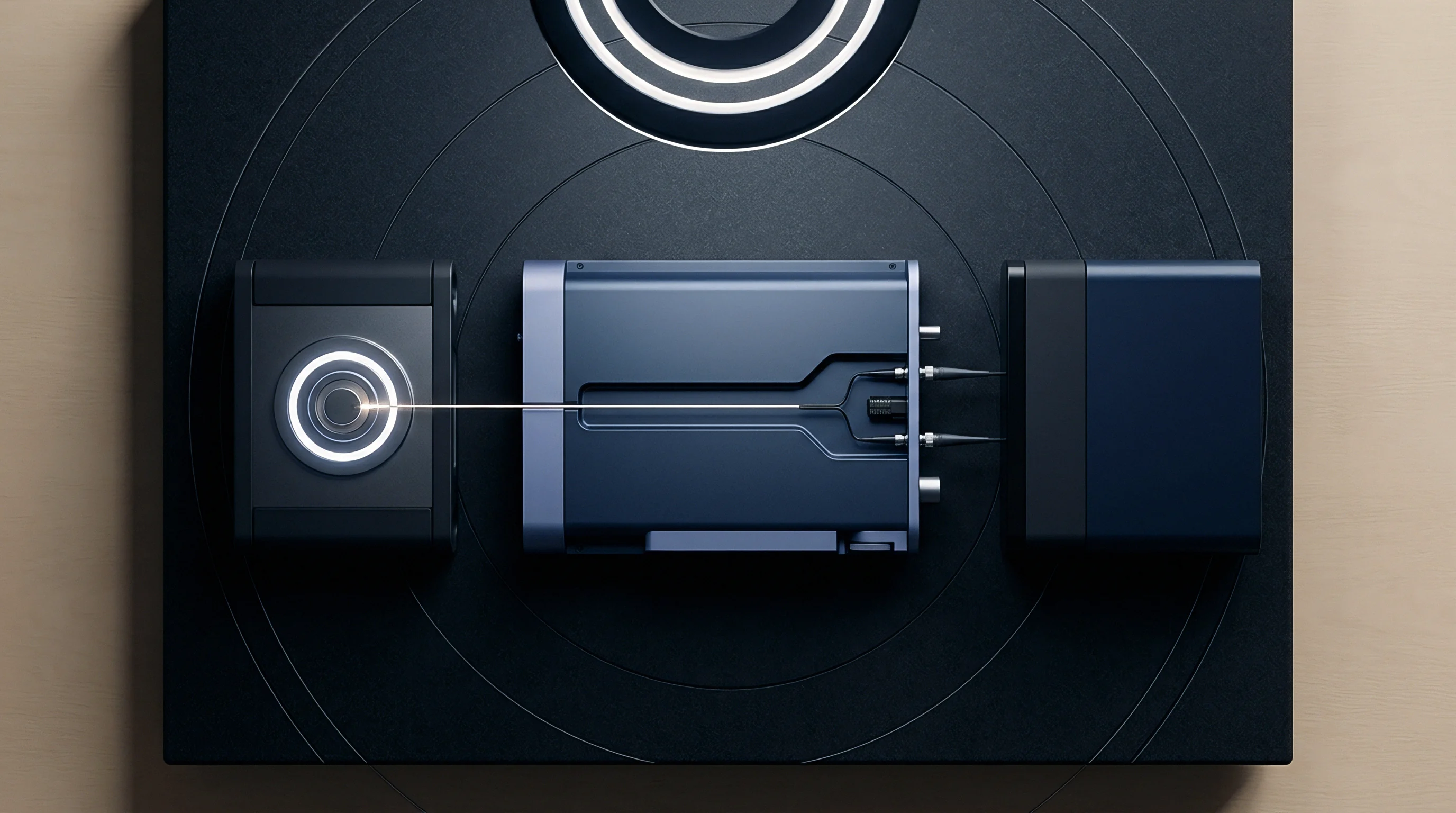
Metrology inside Climate Controlled Compact Antenna Test Ranges
Quantifying thermal distortion requires high-resolution 3D radiation scans. Multi-axis positioners step the radar module through fine angular increments while recording channel-phase and amplitude data. These sweeps map equivalent isotropically radiated power, peak gain, 3-dB beamwidth, cross-polarization rejection, and sidelobe levels across stabilized thermal states.
Evaluating transient thermal behavior is essential for assessing cold startup performance. When a radar initializes at negative 40 degrees Celsius, MMIC power dissipation rapidly heats the center of the circuit board while the outer edges and radome remain cold. This sharp thermal gradient drives transient dielectric variations across the substrate, causing time-varying beam squint during the initial ten minutes of operation.
Continuous pattern sweeps during warm-up are required to detect these transient performance drops.
ISO 16750-4 dictates thermal ramp rates and dwell times for automotive electronic equipment verification campaigns.
ETSI EN 302 264 governs RF performance limits for 77 to 81 GHz radar equipment. Radiated power spectral density masks impose tight limits on out-of-band and spurious emissions. Because permittivity drift can push the frequency response of planar bandpass filters toward allocated band edges, chamber testing must verify mask compliance across the full thermal envelope.

Radiated Pattern Measurement Setup and Thermal Chamber Integration
Accurate measurement requires careful integration of climate conditioning equipment within the test range quiet zone. The following sequence details the process for thermal radiation testing of automotive radar assemblies.
- Mount the radar unit securely on a low-permittivity foam support pedestal inside the Compact Antenna Test Range quiet zone.
- Install the expanded polypropylene thermal shroud around the device under test, keeping air supply lines clear of the turntable rotation arc.
- Connect temperature-stable fiber optic data lines to the radar interface port to extract raw detection data without distorting the RF field.
- Calibrate the quiet zone phase front at room temperature using a calibrated millimeter-wave reference horn antenna.
- Engage the climate control system to stabilize air temperature at negative 40 degrees Celsius, holding a two-hour thermal dwell to reach internal equilibrium.
- Execute full 3D azimuth and elevation radiation pattern scans, recording power levels, mainlobe pointing angles, and null positions across all channels.
- Increase temperature in 20-degree increments up to 125 degrees Celsius, repeating radiated pattern scans at each step once thermal equilibrium is reached.
- Process the collected phase and amplitude matrices to plot boresight error trends and gain variations across the operational thermal envelope.
Thermal chamber metrology establishes the actual operational limits of antenna materials under simulated conditions, providing the empirical data required to validate material selection against pointing accuracy targets.
Isolating internal dielectric drift from mechanical housing deformation during high-temperature radiated scans requires synchronized optical tracking alongside phase measurements.

Arithmetic
Evaluating the impact of dielectric drift on array performance requires calculating cumulative phase shift and beam pointing deviation. Consider an eight-element linear series-fed patch array designed for 76.5 GHz, where the free-space wavelength is 3.9189 millimeters. The microstrip feed lines utilize a high-frequency laminate with a nominal relative permittivity of 3.00 at 25 degrees Celsius, yielding an effective dielectric constant of approximately 2.35 for a 50-ohm line at room temperature.
At 25 degrees Celsius, phase velocity along the microstrip equals vacuum light speed divided by the square root of the effective dielectric constant, or 1.9555 times 10 to the 8th power meters per second. Element spacing is selected to produce a 360-degree phase shift at design frequency for broadside radiation ~ matching one guided wavelength along the feed line, or 2.5562 millimeters at 25 degrees Celsius.
Evaluating performance across a 100 Kelvin temperature rise (from 25 degrees Celsius to 125 degrees Celsius) involves comparing three candidate substrates: Option A uses a woven-glass PTFE laminate with a thermal dielectric coefficient of negative 160 ppm per degree Celsius; Option B uses a ceramic-filled PTFE laminate at negative 10 ppm per degree Celsius; and Option C uses a thermoset hydrocarbon composite at positive 45 ppm per degree Celsius.
For Option A, a 100 Kelvin temperature rise reduces relative permittivity by 0.0480 (nominal permittivity times coefficient times delta T), shifting relative permittivity to 2.9520 at 125 degrees Celsius. The effective dielectric constant drops to 2.3168. Phase velocity increases to 1.9695 times 10 to the 8th power meters per second, extending guided wavelength to 2.5745 millimeters.
With element spacing fixed during manufacturing at 2.5562 millimeters, the electrical phase shift between adjacent elements at 125 degrees Celsius drops below 360 degrees. Calculating two pi times frequency times element spacing divided by the new phase velocity gives 6.2396 radians (357.50 degrees) ~ creating an inter-element phase error of negative 2.50 degrees.
Across an eight-element array containing seven feed segments, this error accumulates progressively along the line. Phase error at the final element reaches seven times negative 2.50 degrees, totaling negative 17.50 degrees and tilting the radiated phase front away from broadside.
Beam squint resulting from this phase error follows array factor theory: the sine of the squint angle equals inter-element phase error in radians divided by free-space wavenumber times physical element spacing. At 76.5 GHz, free-space wavenumber is 1603.32 radians per meter, giving a product of wavenumber and spacing of 4.0984 radians. Dividing the negative 0.0436 radian inter-element error yields negative 0.01064, corresponding to a beam squint angle of negative 0.610 degrees.
A beam squint of negative 0.610 degrees rotates the main beam vector 0.610 degrees off mechanical boresight. At a standard autonomous emergency braking evaluation range of 150 meters, lateral dislocation equals range times the tangent of the squint angle ~ 150 meters times tangent of 0.610 degrees, or 1.597 meters laterally.
| Substrate Candidate | Thermal Dielectric Coefficient (ppm/°C) | Effective Dielectric Constant at 125°C | Inter-Element Phase Error at 125°C (Degrees) | Cumulative Terminal Phase Error (Degrees) | Array Beam Squint Angle (Degrees) | Spatial Target Dislocation at 150m (Meters) |
|---|---|---|---|---|---|---|
| Option A: Woven Glass PTFE | -160 | 2.3168 | -2.50 | -17.50 | -0.610 | 1.597 |
| Option B: Ceramic PTFE | -10 | 2.3479 | -0.16 | -1.12 | -0.039 | 0.102 |
| Option C: Hydrocarbon Resin | +45 | 2.3642 | +0.69 | +4.83 | +0.168 | 0.440 |
Option B demonstrates significantly greater thermal stability. A coefficient of negative 10 ppm per degree Celsius results in a permittivity drop of 0.0030, moving the effective dielectric constant to 2.3479. Inter-element phase error decreases to negative 0.16 degrees, accumulating to negative 1.12 degrees at the final element.
Beam squint drops to negative 0.039 degrees, keeping spatial dislocation to 0.102 meters at 150 meters ~ well within lane boundaries.
Option C exhibits positive phase drift. Its coefficient of positive 45 ppm per degree Celsius increases effective dielectric constant to 2.3642 at 125 degrees Celsius, slowing wave propagation. Inter-element phase error shifts to positive 0.69 degrees, building to positive 4.83 degrees at the terminal element.
Beam squint moves to positive 0.168 degrees, translating to a lateral target dislocation of positive 0.440 meters at 150 meters.
Temperature-dependent loss tangent variations also degrade radiation efficiency. For Option A, nominal loss tangent rises from 0.0013 at room temperature to 0.0018 at 125 degrees Celsius. Feed line attenuation increases from 0.45 dB per centimeter at 25 degrees Celsius to 0.62 dB per centimeter at 125 degrees Celsius.
Across a total series feed length of 17.89 millimeters, insertion loss climbs from 0.805 dB to 1.109 dB ~ a 0.304 dB drop in radiated power that directly degrades detection range.
These calculations highlight the substrate’s thermal dielectric coefficient as the primary driver of pointing accuracy in series-fed arrays. Specifying laminates with thermal coefficients above 50 ppm per degree Celsius introduces pointing errors severe enough to necessitate software compensation or non-series corporate feed topologies.

Approval
Automotive radar equipment must satisfy rigorous RF regulatory frameworks prior to commercial release. Type approval authorities evaluate compliance against standards designed to protect spectrum allocations and prevent harmful interference. Temperature-driven permittivity shifts directly affect compliance outcomes by altering occupied bandwidth, center frequency stability, peak radiated power, and out-of-band emissions.
Under European Union Radio Equipment Directive 2014/53/EU, 76 to 81 GHz automotive radars undergo testing against harmonized standards ETSI EN 302 264 and ETSI EN 301 091-1. Occupied bandwidth must remain strictly within allocated band edges under all conditions, including ISO 16750-4 thermal extremes. Permittivity drift that shifts local oscillator tuning or filter passbands can cause radiated power to spill beyond legal boundaries, triggering market surveillance audit failures.
In the United States, FCC rules under Title 47 CFR Part 95 Subpart M govern 76 to 81 GHz radar operation. Section 95.3379 defines explicit emission limits, including a maximum equivalent isotropically radiated power of 55 dBm peak and 50 dBm average. Permittivity changes that alter antenna gain or beam focus across temperature directly affect compliance: gain drops reduce detection range, while unintended gain spikes can breach legal limits and risk regulatory enforcement or grant revocation.
Regulatory grants apply strictly to the hardware configuration evaluated during type approval. Modifying radome materials, changing PCB laminate suppliers, or altering housing geometry to correct thermal distortion invalidates existing equipment authorizations. The FCC treats material modifications affecting RF performance under permissive change rules; introducing a radome material with a different thermal permittivity coefficient requires a Class II Permissive Change filing supported by radiated test reports demonstrating full Part 95M compliance.
Global compliance demands aligned filing schedules across multiple regulatory bodies. Obtaining approvals from the FCC, European notified bodies, China’s State Radio Regulatory Commission, and Japan’s Giteki requires comprehensive test dossiers containing environmental stability data. Engineering teams must schedule adequate chamber time for radiated testing across full operating temperature ranges, as unexpected high-temperature beam distortion failures halt approval pipelines and delay vehicle start-of-production.
Vehicle integration contracts explicitly assign compliance liability to radar suppliers, requiring assemblies to maintain valid modular or system-level grants in all target markets. A standard clause reads: The supplier warrants that the radar sensor assembly fully complies with all applicable radio frequency regulatory standards, including ETSI EN 302 264 and FCC Part 95M, across the entire operating temperature range from negative 40 degrees Celsius to 125 degrees Celsius, and agrees to bear all financial costs associated with permissive change filings or field recalls resulting from thermal non-compliance.