Meaning
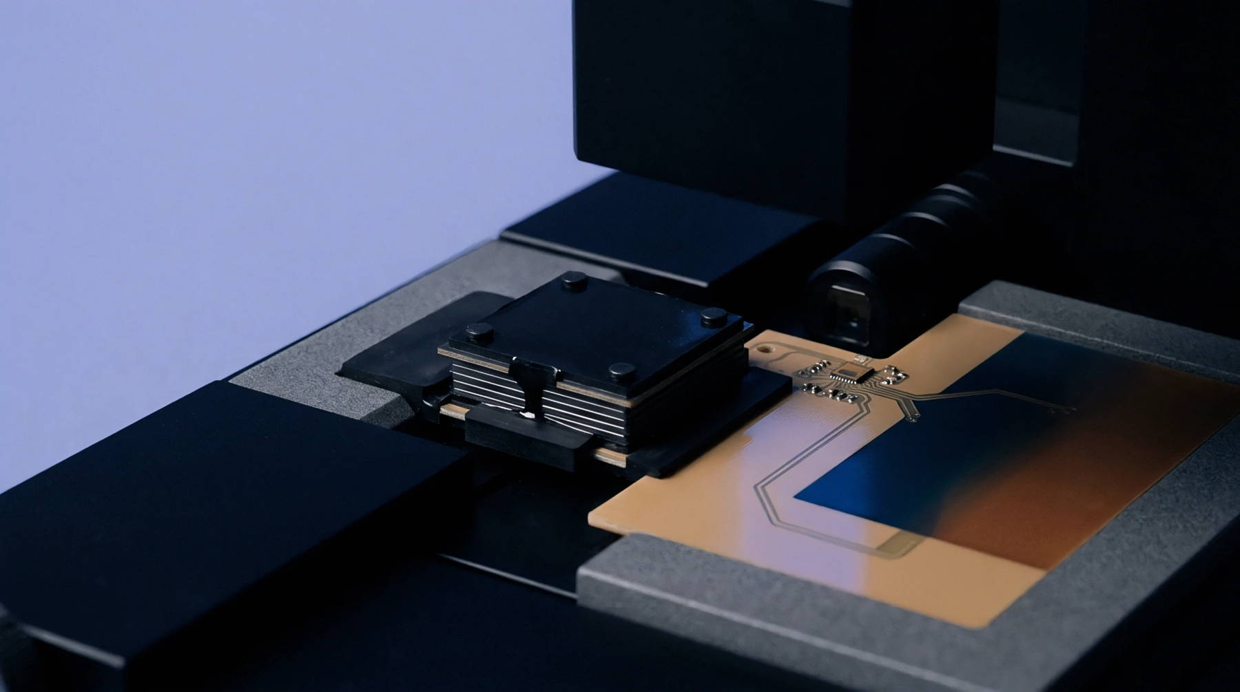
Firmware alignment designates the synchronization procedure matching binary code versions across the microcontroller, peripheral ICs, and radio modules during production board testing. Radio hardware requires exact version parity between baseband processors and companion memory chips to satisfy regulatory emission masks and frequency hopping tolerances. Production lines execute this synchronization immediately after automated optical inspection before the final enclosure goes on the assembly jig.
Engineers define the valid software baseline inside the manufacturing execution system database, which pushes exact binary images down through the test fixture pogo pins.
Version Parity
Production facilities enforce strict revision matching to prevent RF calibration drift during the final functional verification stage. Companion memory devices store calibration constants linked to specific binary builds, meaning a mismatched microcode load invalidates thermal compensation tables. Test fixtures read the hardware fuse bytes inside the processor and compare those values against the release manifest stored on the local server.
A mismatch halts the programming sequence automatically, flagging the printed circuit board assembly for manual rework before the RF shielding can be installed.
Thermal Budget
Thermal dissipation characteristics change when uncalibrated code loops execute excessive polling cycles inside the main processing core. Radio frequency modules generate localized hot spots that alter crystal oscillator frequencies during continuous transmission tests. Firmware alignment updates power management registers to restrict clock speeds until package temperature sensors stabilize within safe operating thresholds.
Production test operators monitor thermal imaging cameras while the board runs the diagnostic script to confirm the updated binary does not exceed the mechanical enclosure limits.
Interface Verification
Serial peripheral interface buses transfer the binary packages from the flashing tool to the target memory banks under strict timing constraints. Signal integrity degrades when capacitive loads from test fixture cables alter clock edges during high speed programming passes. Verification routines check parity bits returned by the peripheral chips to confirm error free transfer before releasing the reset line.
Final sign off occurs when the radio stack successfully completes loopback testing through the test fixture antenna coupler at nominal voltage.