Meaning
An electromagnetic phenomenon occurs when the proximity of metallic structures or human tissue shifts the resonant frequency of an integrated antenna away from its intended operating band. This impedance mismatch arises because the conductive ground plane of the printed circuit board acts as an active participant in the antenna radiation mechanism. Managing ground plane detuning is essential to prevent severe losses in wireless range, throughput and battery life in compact connected devices.
It governs the design of antenna matching networks, housing clearances and board dimensions during the physical integration of the radio. This phenomenon does not apply to devices that utilize external, balanced antennas that do not rely on the system board for their radiation pattern.
Hardware Architecture
Antenna performance in a compact smart device is heavily dependent on the layout and size of the printed circuit board ground plane. The ground plane forms the counterpoise of the antenna system, meaning that any change to its physical dimensions or environment alters the resonant frequency of the antenna. When a user holds the device, or when the device is mounted on a metal surface, the electric fields are compressed, causing the resonant frequency to shift downward.
This frequency shift results in a high voltage standing wave ratio, which means that much of the transmitter power is reflected back into the transceiver instead of being radiated into the air. To mitigate this effect, hardware engineers must design a multi component matching network that can tolerate these environmental variations. They also maximize the distance between the antenna element and other internal metal components, such as the battery or shielding cans.
Operational Impact
Smart devices must maintain a stable wireless connection even when operated in unpredictable physical configurations. If ground plane detuning occurs, the resulting impedance mismatch reduces the radiated output power and degrades the receiver sensitivity. To compensate for this signal loss, the transceiver must increase its amplification levels, which draws more current from the battery and accelerates thermal buildup.
In severe cases, the device may drop the wireless connection entirely, leading to data loss and increased latency as the system attempts to reconnect. Implementing a dynamic tuning circuit, which adjusts the matching network in real time based on feedback from a sensor, can restore the resonant frequency and protect the wireless link. This dynamic compensation maintains consistent performance across various mounting scenarios and usage profiles.
Verification Protocol
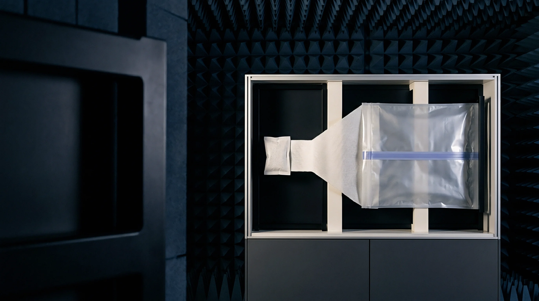
RF engineering laboratories evaluate these detuning effects by measuring the antenna return loss in different mounting configurations. They use vector network analyzers to plot the reflection coefficient across the operating bands while placing the device in simulated user scenarios, such as against a hand phantom or a metal plate. These measurements reveal how far the resonant frequency shifts and allow the engineers to optimize the matching network values for the most common usage case.
The resulting antenna pattern measurements are documented to confirm that the radiated power remains within the limits required by cellular carriers and regulatory authorities. This validation ensures that the device meets its wireless range and battery life targets in the field.