Meaning
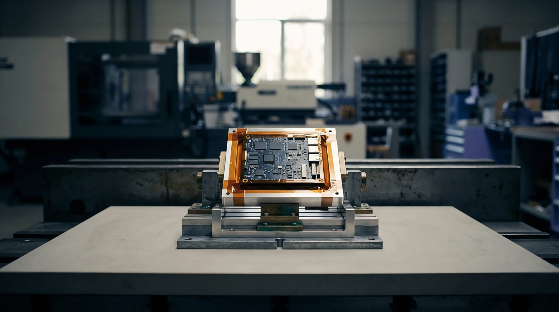
Circuit board assembly houses the integrated radio host by combining baseband processing chips and power amplifiers onto a single carrier board. This radio architecture relies on a shared metallic chassis to ground high frequency signals and dissipate thermal loads generated during continuous transmission cycles. Radio frequency engineers calibrate the receiver sensitivity inside this hardware block during final factory testing before the module receives certification.
Thermal Load
Heat dissipation dictates the mechanical boundaries of the radio enclosure when power output increases past five watts. Copper ground planes transfer thermal energy away from the radio frequency integrated circuit toward the external housing. Convection airflow prevents junction temperatures from exceeding the maximum rating specified in the silicon manufacturer datasheet.
Interface Margin
Voltage standing wave ratio measurements verify that antenna connectors match the fifty ohm impedance of the transceiver board. Signal degradation occurs if coaxial cables experience bending radii tighter than the minimum limit defined in the mechanical specification. Transmission power drops significantly when insertion loss across the bulkhead connector exceeds acceptable limits.
Compliance Verification
Regulatory testing laboratories subject the completed transceiver assembly to radiated emissions sweeps before granting commercial market access. Harmonic suppression filters attenuate out of band signals to satisfy regional spectrum management mandates. Spectrum analyzers capture spurious emissions during maximum modulation sweeps to ensure compliance with strict government broadcasting standards.