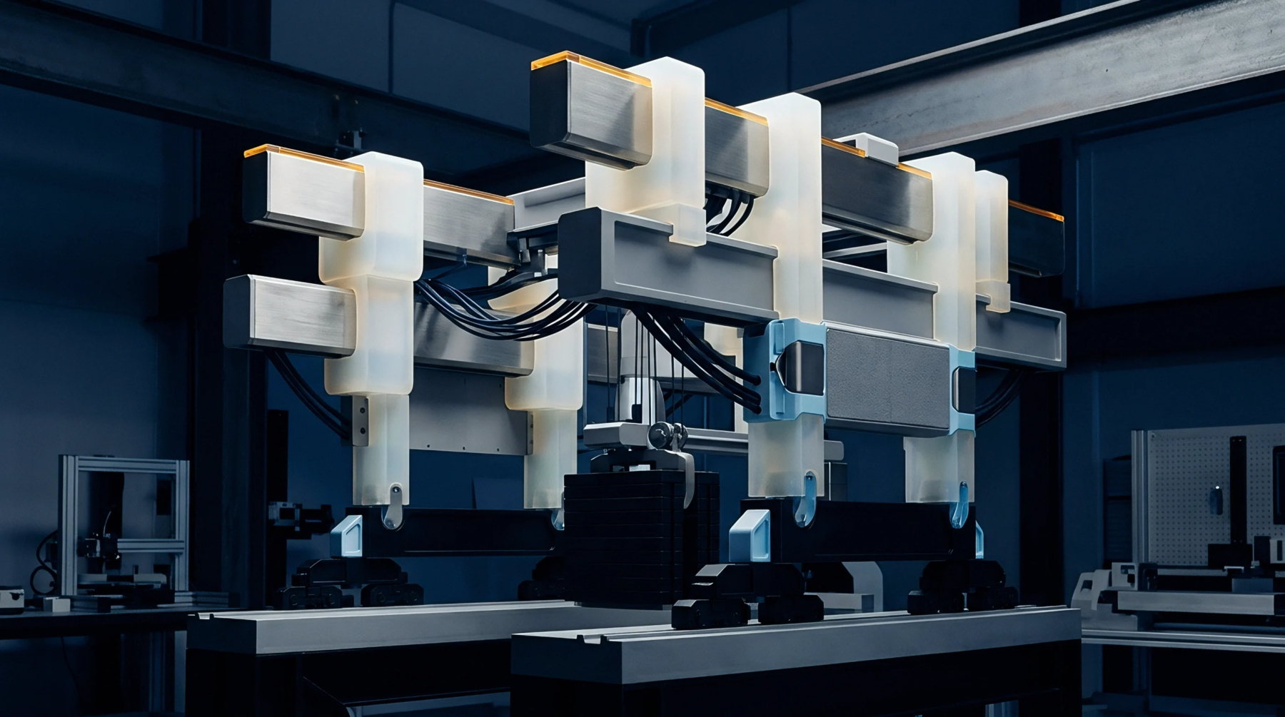
Active In-Situ Temperature Compensation for Multi-Axis Continuous Sensor Test Fixtures
Active in-situ thermoelectric compensation stabilizes multi-axis sensor test platens, preventing dynamic thermal gradients from corrupting inertial calibration.
A micro-electro-mechanical system integrates multiple orthogonal accelerometers and gyroscopic rate sensors inside a single package to measure linear acceleration and angular velocity across spatial dimensions. Utilizing suspended silicon proof masses and capacitive interdigital fingers, a multi-axis inertial sensor detects motion along three perpendicular linear axes and three rotational axes to quantify spatial orientation. The device provides position, motion detection and dead-reckoning data to processing engines within automotive, navigation and smart mobile hardware.
The operational framework terminates when input accelerations exceed proof mass physical displacement stops or when vibration frequencies overlap with the mechanical resonance of the internal sensing comb drives.
Micromachined silicon structures convert physical movement into differential electrical capacitance signals via precision balanced comb arrays. Within a typical multi-axis inertial sensor, capacitive variations caused by the displacement of a seismic mass under inertial loading generate minute electrical charges. Application-specific integrated circuits stacked directly above or placed adjacent to the MEMS die convert these femtofarad-scale capacitance changes into digital words through low-noise charge amplifiers and high-resolution analog-to-digital converters.
Internal drive circuits sustain continuous oscillation of gyroscopic masses, measuring Coriolis forces induced during rotational movement. Differential drive designs reject common-mode external shocks and linear accelerations, ensuring that rotational rate readings remain isolated from simultaneous linear shocks during high-g transient events.
Geometric imperfections and mechanical alignment tolerances during silicon etching introduce unwanted cross-axis sensitivity into measurement channels. Movement along a single linear coordinate can induce subtle parasitic deflections on orthogonal proof masses, generating false motion vectors across adjacent digital output registers. Thermal variations further degrade accuracy by introducing zero-rate output drift and scale factor errors, as package expansion exerts uneven mechanical stress across the silicon die attach.
Firmware compensation routines use internal calibration matrices to eliminate linear cross-axis coupling, but high-amplitude package warpage caused by soldering stresses can introduce non-linear response shifts that evade static polynomial compensation models.
Integration requirements dictate rigid surface-mount soldering guidelines and specific board placement protocols to prevent mechanical stress transfer from the host printed circuit board. Device engineers inspect the sensor assembly using automated test handlers capable of rotating the package across precise angular profiles while reading digital registers. The manufacturer provides a factory calibration certificate recording baseline offset errors, cross-axis sensitivity percentages and sensitivity drift coefficients across operating temperatures.
Verification teams audit these parameters within system acceptance test files, verifying that the sensor meets noise spectral density targets and zero-rate bias limits before enabling fusion algorithms inside the system processor.
Active in-situ thermoelectric compensation stabilizes multi-axis sensor test platens, preventing dynamic thermal gradients from corrupting inertial calibration.
Expertise is a utility, not a secret. sentiention™ publishes its working knowledge as open reference: intelligence layer covering the materials it sources, the markets it enters, and the reference that serves both.