Meaning
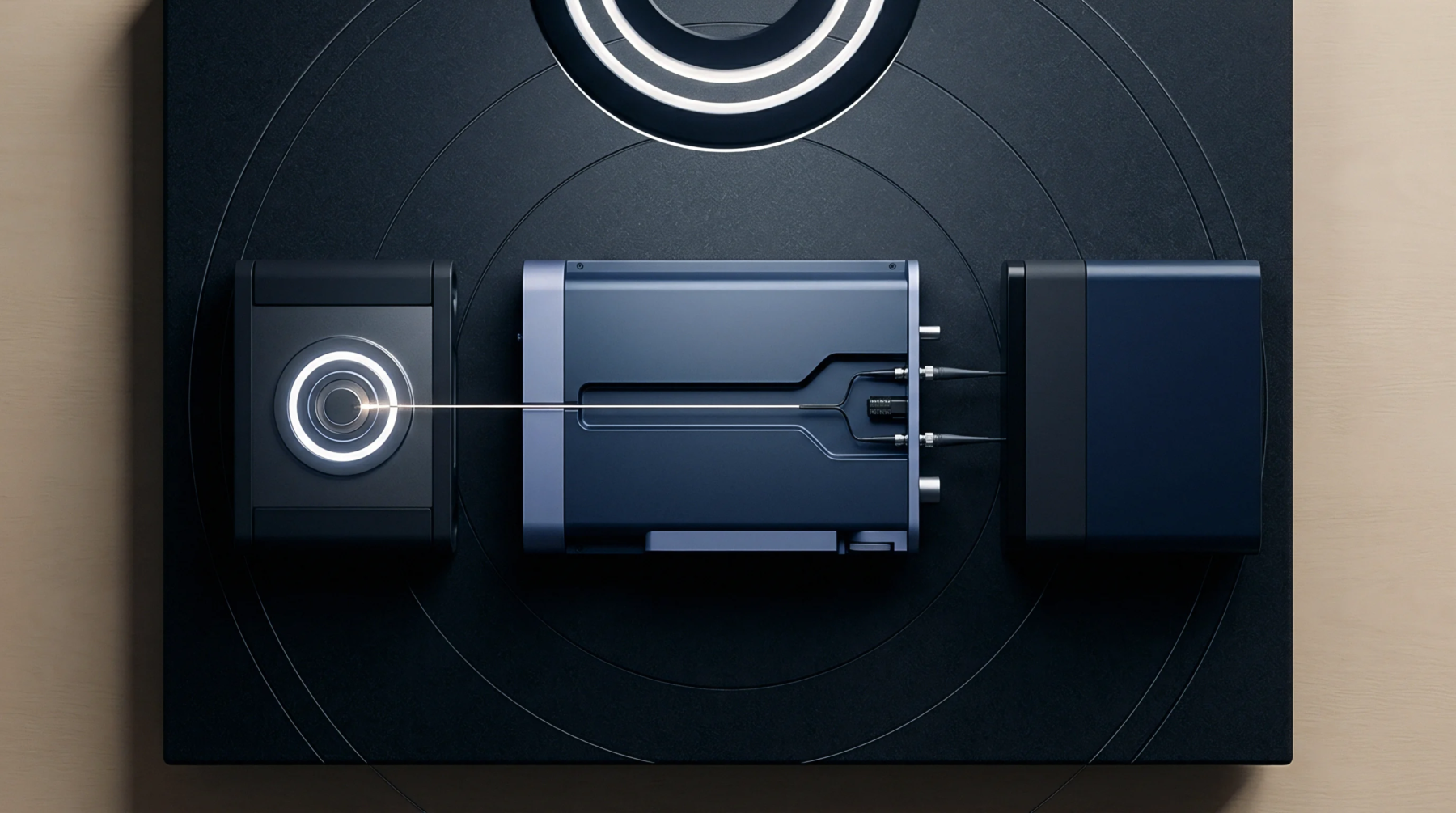
Electro-optical assemblies responsible for capturing external physical images, reading barcodes, or registering biometric patterns interface directly with central processing logic and structural housing components inside a host hardware platform. Mechanical, electrical, and optical scan head integration aligns physical sensors, focusing optics, internal illumination light-emitting diodes, and high-speed data buses into a cohesive product enclosure. This process applies to embedded imaging engines, laser line scanners, and infrared optical sensors integrated into handheld or fixed industrial products.
Technical boundaries end at external lens window coatings and peripheral host processors, excluding backend database management systems and higher-level inventory processing software.
Optical Alignment
Internal component positioning requires sub-millimeter precision to ensure optical paths remain clear of enclosure shadowing, internal light leaks, and focal distortions. Within scan head integration, the physical lens barrel must align precisely with external housing exit windows while maintaining specified working distances to target focal planes. Internal illumination reflections must never bounce back into the sensor aperture from protective window glass surfaces, as backscatter saturates image pixels and ruins decoding rates.
Optical engineers enforce strict exit window angles, multi-layer anti-reflective coatings, and physical rubber light baffles between the receiver and transmitter components. Slight mechanical mounting offsets trigger optical aberrations that degrade reading performance across high-density two-dimensional codes.
Thermal Dissipation
Compact industrial housings present severe heat challenges when optical engines activate high-power illumination arrays during continuous operation. During scan head integration, thermal interfaces route heat away from internal camera sensor dies and illumination light-emitting diodes toward external housing heat spreaders. Excessive internal heat shifts the spectral wavelength of illumination diodes, introduces optical focus drift through thermal expansion of plastic lenses, and increases sensor noise floors.
Conduction paths often employ custom die-cut thermal gap pads or copper heat sinks that must maintain contact without exerting mechanical stress on delicate optics. Thermal design reviews verify that maximum continuous scanning duty cycles do not breach the component operating limits established by optical engine manufacturers.
Protocol Handshake
Data interchange between the imaging engine and the main logic board relies on serial peripheral interfaces, Universal Serial Bus lines, or camera serial interface connections. Modern scan head integration requires precise hardware trigger synchronization to align illumination strobe pulses with internal global shutter exposure sequences. Configuration commands move across bidirectional serial communication links to dynamically set image gains, exposure times, and decode decoding zones based on target operational contexts.
Power supply rails dedicated to the scanning core must incorporate discrete low-dropout regulators and ferrite filtering to isolate noisy digital processors from sensitive optical readouts. Integration teams sign off on hardware delivery via bus timing margin captures, current draw profiles, and formal decode latency reports.