Meaning
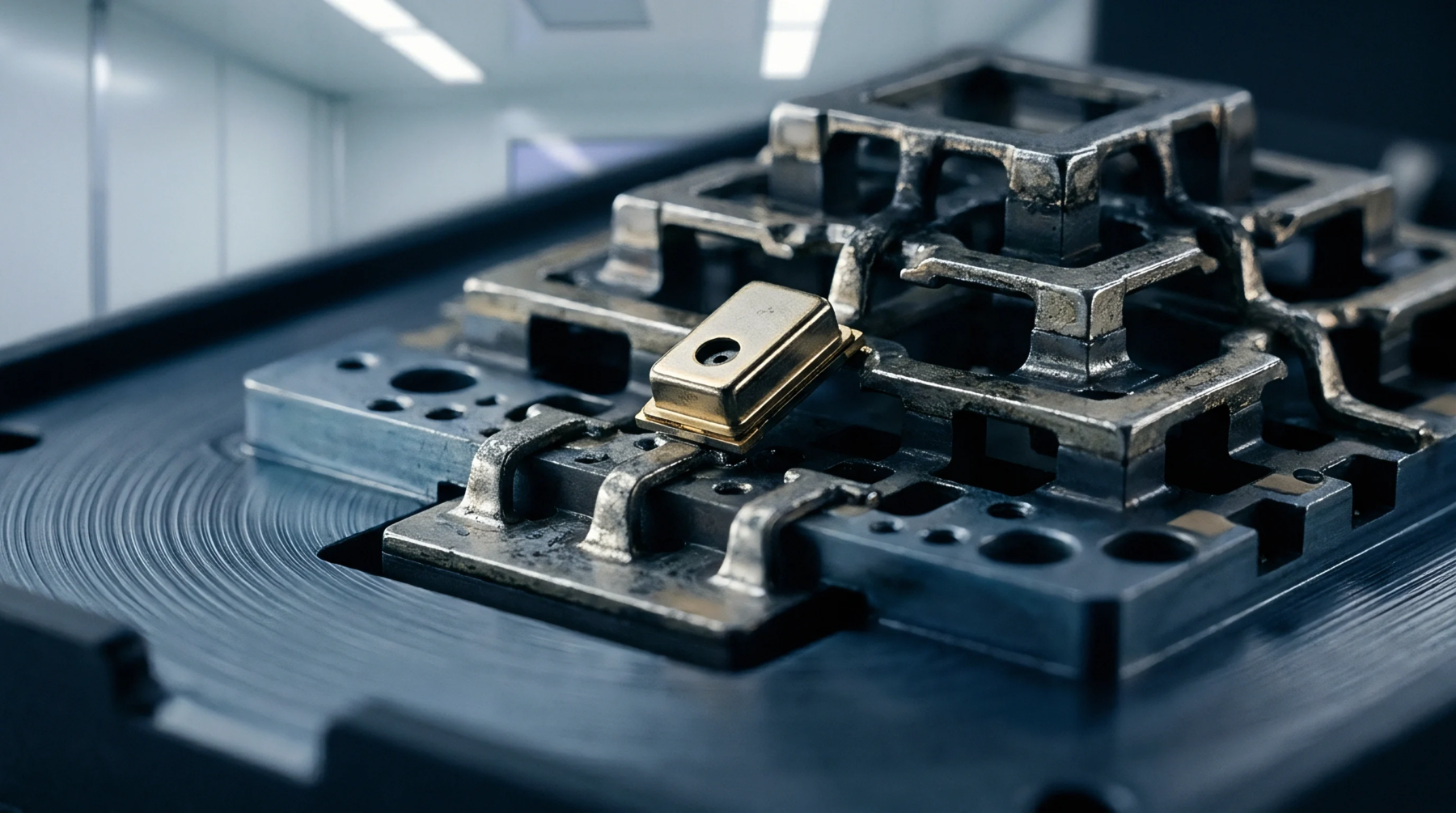
Physical configuration defines the spatial arrangement and internal clearance of a metallic enclosure designed to contain electromagnetic interference within high-frequency circuits. Shielding can geometry dictates the volume available for board-mounted components and determines the specific resonant modes that influence signal integrity. Manufacturers design these boundaries to maintain a gap between the conductive wall and active traces to prevent parasitic capacitance.
Mechanical Constraint
Designers evaluate this enclosure shape against the thermal dissipation requirements of underlying power-sensitive semiconductors. The distance from the top of an integrated circuit to the underside of the lid establishes the airflow path required for passive or active cooling. Tall walls provide clearance for bulky capacitors but increase the surface area prone to internal reflections that destabilize local oscillators.
Engineers verify these physical parameters during the early design simulation phase to prevent crosstalk between adjacent radio frequency stages.
Assembly Fit
Final system integration relies on the precision of the solder footprint alignment and the structural stiffness of the cover tabs. Proper shielding can geometry ensures the enclosure seats flush against the ground plane to create a low-impedance electrical contact. Inadequate contact forces or uneven surface flatness prevents the formation of a continuous electrical barrier around the circuit.
Compliance Metric
Regulatory bodies assess the effectiveness of the containment based on the total suppression of radiated emissions through the seams of the metal housing. Radiated energy leakage correlates with the precision of the aperture sizes and the uniformity of the wall heights. Tight control over these dimensions minimizes the tuning effort during the final electromagnetic compatibility certification process.