Automated Assembly Tooling Calibration Decay Analysis and Preventative Maintenance
Dynamic calibration decay analysis and cycle-based preventative maintenance prevent latent joint failures and high scrap costs in automated module assembly.


Wear

Measurement Drift across Repetitive Fastening Cycles
Continuous thermal and mechanical loading erodes baseline torque and positioning accuracy in electric nutrunners and robotic end effectors. Surface wear across planetary gearsets, ball-screw drives, and rotary torque transducers produces a creeping measurement offset. Tooling engineers treat this shift as calibration decay, logging cycle counts to chart its progression.
An electric transducer rated for 0.5 to 10.0 Newton-meters typically drifts out of nominal tolerance somewhere between 50,000 and 150,000 cycles, largely dictated by joint stiffness. Hard joints turning less than 30 degrees bounce shock energy directly into the drive motor, pitting gear teeth early. Soft joints with over 720 degrees of rotation dump sustained heat into the transducer rotor instead, pulling the strain-gauge zero balance off center.
Positional drift along Cartesian axes follows an equivalent mechanical path. Lead screws develop localized axial play across the specific stroke segment where module insertion takes place. In harmonic drive gearheads, flexspline teeth thin out after roughly 4,000 operating hours, opening angular backlash beyond 1.5 arcminutes.
Stations routinely fall out of process capability long before a hard mechanical seizure stops the line. By that point, positional runout has already begun bending peripheral lead frames, cracking solder joints during casing presses, and chewing up miniature connector housings.
Strain-gauge bridge output shifts by roughly 0.02 percent of full scale per degree Celsius outside the compensated temperature band of 15 to 35 degrees Celsius.
Turnkey assembly sourcing creates serious warranty exposure whenever a plant runs equipment to failure instead of tracking mechanical drift. Wear-induced drift produces intermittent assembly defects, the sort of latent electrical faults that slip clean through functional testing. A casing torqued to an actual 0.6 Newton-meters against a 1.1 Newton-meters specification will still seal well enough to pass an end-of-line dry air pressure decay test.
In the field, however, ordinary thermal expansion breaks the gasket seal, pulling moisture directly into RF traces and high-density interconnect vias.
Contracts typically assign preventative maintenance routines to the manufacturing partner, but enforcement relies on verifiable data. Facilities running without dynamic torque auditing frequently clear calibration date stamps in controller software without placing the tool on an external laboratory beam. The bypass keeps gross output numbers steady while true fastening capability degrades well below specification.
Engineers establish structural wear limits by pairing cycle volume against empirical joint stiffness distributions.


Decay

Statistical Characterization of Dynamic Measurement Loss
Detecting tool degradation requires real-time statistical process control fed by live line telemetry, not occasional static bench checks. Capability indices ~ specifically Cp and Cpk ~ reveal kinematic deterioration before parts drift past upper or lower specification limits. Modern direct-current spindles capture angle-of-turn alongside torque profiles on every drive.
When mean delivered torque wanders from nominal target, systematic drift is underway; when standard deviation widens, the culprit is usually mechanical play, brinelled bearings, or dynamic stick-slip friction.
| Capability Index | Mathematical Criterion | Tool Operational Status | Recommended Factory Intervention |
|---|---|---|---|
| Cpk Above 1.67 | Upper and lower limits exceed 5 standard deviations from mean | Nominal operating state with full statistical control | Standard weekly inline verification against baseline transducer |
| Cpk 1.33 to 1.67 | Process limits sit between 4 and 5 standard deviations | Marginal tolerance consumption from normal mechanical wear | Shorten tool verification interval from 7 days down to 48 hours |
| Cpk 1.00 to 1.33 | Process limits sit between 3 and 4 standard deviations | Active calibration decay requiring tooling adjustment | Immediate dynamic bench calibration and offset compensation |
| Cpk Below 1.00 | Process limits narrower than 3 standard deviations | Non-capable system producing defect units across shifts | Line stoppage, structural overhaul, and spindle replacement |
Torque-rate curves reveal structural decay mechanics across different subassemblies. A compliant joint allows linear energy absorption, generating a smooth curve from snug torque to final shutoff. Progressive wear in spindle drive clutches distorts this curve, introducing transient torque spikes that trigger false motor shutoffs.
The controller registers target torque achievement, but actual clamping force remains inadequate because kinetic energy dissipated as friction rather than residual fastener tension. The assembly station ships units with loose structural retainers despite pristine digital pass logs.
Calibration decay also governs automatic dispensing equipment applying underfill, thermal interface materials, and structural adhesives. Progressive orifice wear in positive displacement valves increases dispensed bead cross-section by 8 to 15 percent over 500,000 cycles under abrasive, ceramic-filled epoxy usage. Pumping pressure decay from worn piston seals decreases delivered volume, producing dry joints and voids beneath surface-mount radio modules.
Automated optical inspection captures surface area spread, but volumetric drift requires high-precision gravimetric balance audits every shift.
Degradation curves follow distinct exponential, linear, or sudden-break patterns depending on the physical mechanism driving the transducer interface.


Shock

Dynamic Load Limits and Transducer Degradation
Mechanical shock alters sensor geometry instantly, breaking linear decay models through permanent plastic deformation of internal sensing elements. Modern brushless DC screwdrivers incorporate strain-gauge rosettes bonded to a torsion shaft. When an operator drops a handheld tool or an automated Cartesian gantry experiences an axis collision at 400 millimeters per second, peak g-forces bypass mechanical compliance limits.
The transducer shaft experiences shear strains past its elastic limit, producing permanent bridge offset.
Assembly line operators frequently employ hard torque stops to arrest fast-moving pneumatic or electric slides. Repeated deceleration spikes transmit high-frequency vibrations through the tool mounting face into the internal piezoelectric or piezoresistive sensors. The bonding adhesive securing strain gauges to the metallic substrate undergoes fatigue delamination, presenting as erratic sensor output drift during thermal cycling.
The tool may pass a single-point calibration verification at room temperature while failing continuously during line operation under motor thermal load.
A single unmonitored hard stall exceeding 150 percent of rated transducer capacity invalidates calibration certificates regardless of elapsed calendar time.
Mechanical shock also affects axis alignment across automated pick-and-place heads and vacuum nozzles. Pneumatic collet actuators sustain misalignment when handling warped printed circuit boards or misaligned RF shielding cans. A deflection of 0.05 millimeters at the spindle nose multiplies across the tool extension, generating side-loading forces on surface-mount package terminations.
Solder balls on ball grid array wireless chipsets crack during placement when vertical nozzle impact forces exceed component packaging limits.
Preventative tooling controls require inline triaxial accelerometers permanently affixed to automated tooling mounts. Vibration data streaming to industrial automation controllers triggers mandatory calibration routines whenever measured shock levels exceed preset thresholds. Bypassing these alerts results in immediate tool drift and silent assembly failure.
Sudden drops in line yield are often attributed to incoming component tolerances when unrecorded tool crashes have actually shifted Cartesian zero positions.


Bench

Metrology Requirements for Shop-Floor Tool Calibration
Dynamic torque calibration demands dedicated metrology hardware compliant with ISO 6789 and VDI/VDE 2647 guidelines. Static bench testing using simple mechanical dial gauges or torque wrenches fails to replicate rotational inertia and dynamic motor braking profiles. A certified mobile calibration bench features an active rotary torque transducer paired with a programmable brake simulator capable of replicating joint stiffness profiles from 5 degrees to 720 degrees of rotation.
The simulator must capture 10,000 samples per second to identify transient torque overshoots caused by controller loop delays.
Tool qualification protocols define specific statistical sampling procedures for inline validation:
- Baseline Environmental Stabilization ~ Tools operate within target production room ambient parameters of 20 to 24 degrees Celsius and 40 to 60 percent relative humidity for two full hours before recording benchmark torque figures.
- Rotary Friction Tare Calculation ~ Mechanical tare cycles run without joint engagement establish parasitic bearing drag resistance across internal spindle bearings.
- Dynamic Fastening Sequences ~ Operators complete twenty-five consecutive fastenings against a calibrated hydraulic or electromagnetic joint simulator configured to replicate production assembly joint stiffness.
- Sample Statistical Derivation ~ Engineers calculate arithmetic mean, range, and standard deviation to establish baseline tool capability indices against specification drawings.
- Non-Volatile Calibration Write ~ Firmware offsets and calibration slope coefficients flash directly into the tool controller memory, locking update timestamps to prevent manual overrides.
Positional calibration for multi-axis Cartesian and SCARA assembly arms utilizes high-precision laser trackers and optical calibration plates. Target fiducials mounted across the machine workspace yield kinematic error mapping across X, Y, and Z axes. Backlash compensation values, ball screw pitch error corrections, and arm deflection coefficients upload into robot controller motion configuration files.
Skipping systematic backlash mapping permits accumulated thermal error to misalign delicate RF connector pins during blind-mate docking procedures.
Sourcing teams must scrutinize tooling calibration logs when reviewing supplier audit dossiers during supplier qualification phases. Many tier-two manufacturing facilities calibrate tooling strictly on a calendar basis every twelve months. Tools operating three shifts per day, six days per week, accrue over 1,500,000 cycles within that interval, spending months operating outside capable limits.
Section 8.5.1 of IATF 16949 dictates that measurement systems undergo comprehensive verification when equipment adjustments alter baseline operating parameters.


Protocol
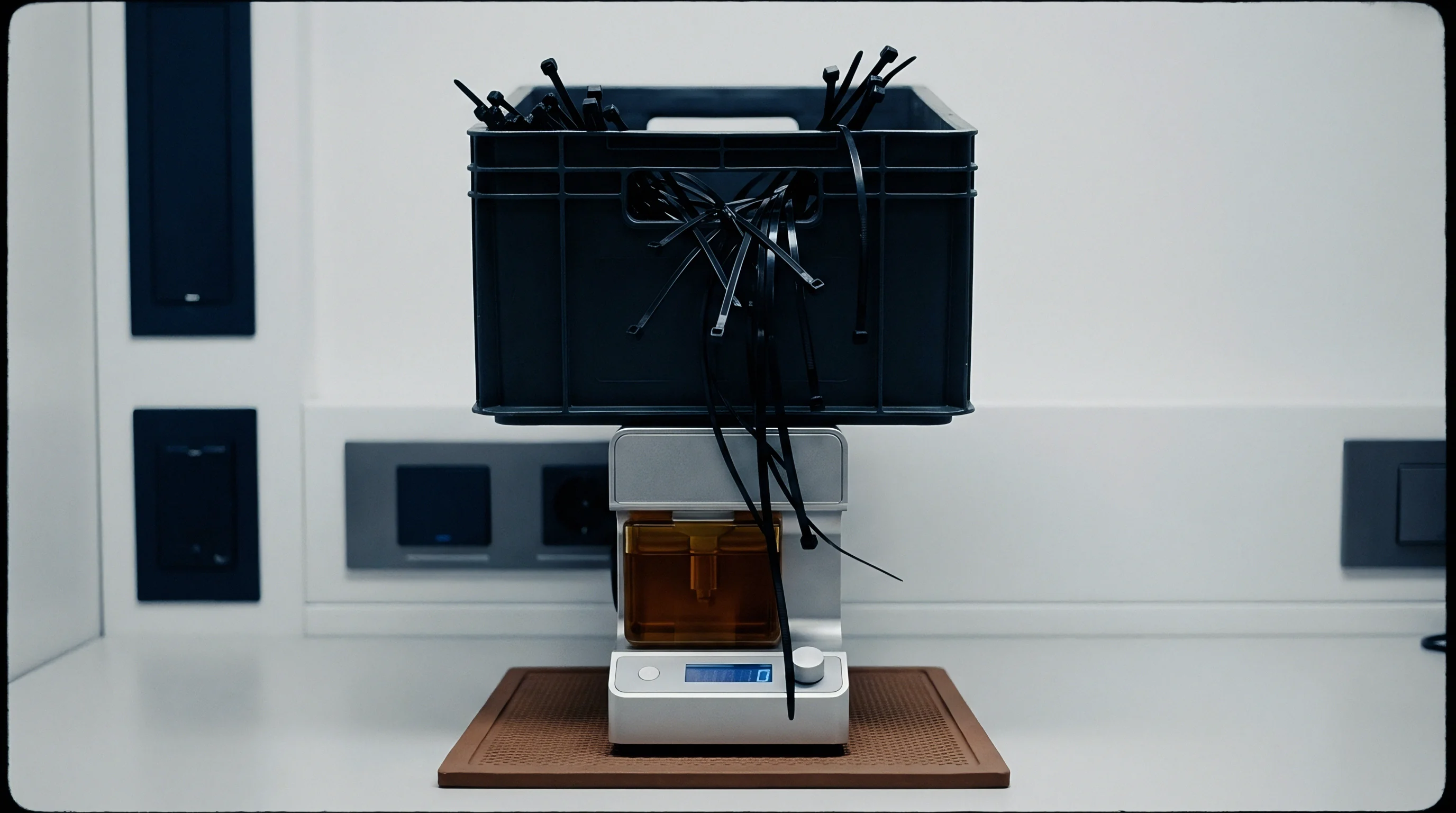
Dynamic Preventative Maintenance Execution Architecture
Industrial assembly lines run deterministic preventative maintenance architectures tied directly to production cycles and statistical process alerts rather than calendar schedules. Automated assembly stations monitor operating currents, acoustic emissions, cycle counts, and motor temperatures to build predictive maintenance models. Spindle motor current draw shifts indicate mechanical friction build-up inside gear assemblies, serving as an automated maintenance trigger before calibration degradation breaches manufacturing tolerances.
| Tool Category | Preventative Interval | Required Inspection Action | Acceptance Criteria |
|---|---|---|---|
| Electric Torque Spindles | 50,000 cycles or 14 operating days | Dynamic torque verification on active rotary simulator | Delivered mean within 2 percent of target; Cm and Cmk above 1.67 |
| SMT Component Placement Nozzles | 100,000 cycles or 7 operating days | Optical tip geometry inspection and vacuum flow decay check | Nozzle tip concentricity under 0.01 mm; vacuum loss under 5 percent |
| Dispensing Valves and Pumps | 250,000 cycles or 30 operating days | Gravimetric shot weight verification and seal replacement | Delivered adhesive mass within 3 percent over 20 consecutive cycles |
| Pneumatic Press-Fit Cylinders | 75,000 cycles or 14 operating days | Load-cell force profile audit and stroke displacement check | Insertion force delivery within 1.5 percent of nominal target |
Maintenance execution requires clear custodial boundaries between factory maintenance technicians, production engineers, and module sourcing representatives. When an electric spindle crosses its preventative cycle limit, the line control software prevents further job execution until an authorized maintenance technician completes verification routines. Bypassing software interlocks requires supervisor overrides that trigger automated compliance notifications to the quality management system.
Physical maintenance protocols demand component tear-down, solvent cleaning of gearsets, replacement of mechanical seals, and re-greasing with specified synthetic lubricants. Applying generic lithium grease into high-speed planetary assemblies alters dynamic viscous drag, throwing off initial calibration values by several percent until mechanical equilibrium returns after hours of run-in time. Factory work instructions must dictate exact lubricant part numbers and measured application masses.
Production tooling operating without documented cycle-based maintenance plans converts planned maintenance downtime into catastrophic line stoppages.
Preventative intervention strategies extend beyond single tools to include fixtures, jigs, and automated optical inspection cameras. An automated assembly station relies on locating pins and pneumatic clamps to hold modules during screwdriving operations. Wear on hardened dowel pins introduces part seating variation, transferring angular misalignment into the fastener thread interface.
Tool calibration remains technically perfect while the fastening angle variance destroys joint structural integrity.
The operational cost of unmanaged calibration decay surfaces during top-level warranty recovery actions when production records demonstrate deliberate avoidance of maintenance thresholds.


Cost

Should Preventative Maintenance Budgets Match Tooling Replacement Values?
Financial analysis of automated assembly tooling maintenance models highlights the trade-off between aggressive preventative maintenance intervals and capital equipment replacement cycles. An enterprise-grade, multi-axis DC nutrunner spindle carries a procurement cost ranging from 8,000 to 14,000 USD, with replacement angle transducers and planetary gear cartridges priced at roughly 3,500 USD per set. An annual preventative maintenance contract encompassing quarterly overhauls, dynamic recalibration, and spare drive heads typically demands 4,000 USD per spindle year.
Neglecting maintenance schedules to preserve short-term factory margins leads to downstream scrap costs that dwarf equipment depreciation figures. A typical high-density wireless module assembly line generates 1,200 finished units per eight-hour shift. If an uncalibrated press-fit actuator delivers excessive mechanical load over three consecutive production shifts, 3,600 units sustain hidden structural fractures across internal ceramic capacitors and RF matching circuits.
Scrap costs for high-complexity telematics or communication modules frequently exceed 45 USD per subassembly, generating over 160,000 USD in direct physical losses within 24 hours.
Sourcing professionals mitigate these exposures by writing explicit preventative maintenance clauses into manufacturing service agreements:
- Dedicated Calibration Capital Allocation ~ Service providers purchase and maintain dedicated dynamic calibration benches on the production floor rather than relying on off-site metrology services.
- Tool Capability Audits ~ Suppliers log cycle-level process capability metrics for all critical fastening and press operations, transmitting raw Cpk data weekly to buyer quality engineering teams.
- Cycle-Based Component Replacement ~ Maintenance teams discard high-wear mechanical elements, including driver bits, vacuum nozzles, and pneumatic seals, at pre-established cycle counts regardless of visual appearance.
- Financial Scrap Indemnification ~ Contracts hold manufacturing facilities financially liable for batch recalls when failure analysis traces component damage back to unverified or out-of-calibration tooling.
Tooling wear analysis requires direct evaluation of maintenance spend against production volume. Amortizing preventative maintenance costs across a high-volume manufacturing run of 500,000 modules adds less than 0.03 USD per unit to total manufacturing costs. Conversely, resolving field warranty claims originating from uncalibrated fastening tools costs upwards of 120 USD per returned product, excluding customer goodwill loss and line certification suspensions.
Sourcing programs must decide whether to fund dedicated factory tooling calibration benches directly or absorb the latent yield risks inherent in shared supplier test infrastructure.