Sourcing Injection Mold Base Standards for Transferable Tooling Design
Specifying global catalog mold bases with standardized platens, pockets, and metallurgy guarantees tools transfer between international presses without remachining.


Plate
Transferable injection tooling fails most frequently at the platen interface. A mold cut to regional shop habits in Dongguan often locks a buyer into that single press hall: clamping slots, sprue spherical radii, and locating ring diameters match local machinery rather than international standards. Building a tool to migrate smoothly between North American, European, and Asian plants requires catalog plate geometries anchored to recognized standards, primarily DME inch, DME metric, or Hasco metric systems.
Platen dimensions and clamp configurations vary widely across press builders.
The clamping flange forms the primary mechanical boundary between machine and mold. North American facilities running under SPI guidelines expect direct clamp slots or ledges sized for standard 5/8-inch or 3/4-inch bolts. European shops operating under Euromap 2 mandate specific platen bolt-hole patterns and clearances calculated from machine tonnage.
When a mold arrives with non-standard edge distances, operators end up using improvised strap clamps. That introduces uneven loads across the parting line, causing flash and cavity deflection during the injection boost phase.
Hasco K-standard plates specified with DIN 1.2312 pre-hardened steel maintain dimensional stability within 0.02 millimeters across production runs spanning multiple machine installations.
Locating rings present the next hurdle during relocation. Platens use a central register bore to line up the machine injection nozzle with the sprue bushing. North American presses standardize on a 3.990-inch (101.35 mm) locating ring with a 0.25-inch flange thickness.
European machines built to Euromap specs take 110-millimeter, 125-millimeter, or 160-millimeter rings, whereas Japanese and Taiwanese presses tend toward 100-millimeter or 120-millimeter registers. Tool drawings should always specify a bolt-on, interchangeable locating ring rather than one machined directly into the top clamp plate.
| Interface Parameter | DME Inch Standard | DME Metric Standard | Hasco Metric Standard | Futaba Metric Standard |
|---|---|---|---|---|
| Locating Ring Outer Diameter | 3.990 in (101.35 mm) | 100 mm / 110 mm / 125 mm | 110 mm / 125 mm / 160 mm | 100 mm / 120 mm |
| Sprue Bushing Spherical Radius | 0.500 in (12.7 mm) or 0.750 in | 15.5 mm or 21.0 mm | 15.5 mm or 40.0 mm | 10.0 mm or 15.0 mm |
| Sprue Orifice Diameter | 0.156 in (3.97 mm) / 0.218 in | 3.5 mm / 4.0 mm / 5.0 mm | 4.0 mm / 5.0 mm | 3.0 mm / 4.0 mm |
| Clamp Slot Flange Thickness | 0.875 in to 1.375 in | 27 mm to 36 mm | 27 mm to 46 mm | 25 mm to 35 mm |
| Standard Base Plate Sizes | 7.875 x 7.875 in to 23.75 x 35.5 in | 156 x 156 mm to 496 x 696 mm | 156 x 156 mm to 596 x 796 mm | 150 x 150 mm to 600 x 800 mm |
Sprue bushings require the same interchangeability. The spherical radius on the machine nozzle tip must seat fully against the concave pocket of the sprue bushing; otherwise, molten polymer drools during barrel decompression or pack-and-hold pressures above 140 megapascals. A North American press typically runs a 0.500-inch (12.7 mm) nozzle radius with an orifice between 0.125 and 0.218 inches.
European machines rely predominantly on a 15.5-millimeter or 21.0-millimeter spherical radius. Seating an imperial nozzle against a metric sprue produces line contact instead of surface contact, which crushes the orifice under clamping tonnage.
- Interchangeable Locating Ring Assemblies with dual-drilled bolt circles accommodate conversion between 101.35-millimeter North American platen bores and 110-millimeter European platen bores through four socket-head cap screws.
- Standardized Clamp Slots milled into the clamping plates eliminate dependency on loose toe clamps by providing dedicated tie-down ledges that match machine platen T-slot spacing.
- Removable Sprue Bushing Retainers enable maintenance staff to swap imperial 0.500-inch radius components for metric 15.5-millimeter variants inside twenty minutes without disassembling the mold cavity block.
- Hoist Ring Metric Thread Tappings machined on four faces conform to DIN 580 hoisting guidelines, preventing freight depots and receiving plants from refusing crane transport due to incompatible lifting hardware.
Transferable mold procurement agreements generally include an explicit stipulation: The mold maker shall supply dual locating rings and alternative-radius sprue bushings in the shipping crate, certified to seat within 0.03 millimeters of the main injection axis under full machine platen tonnage.


Machined pocket cavities are where tool longevity directly affects commercial flexibility. Instead of cutting part geometry straight into the main mold plates, a transferable tool isolates core and cavity features within hardened steel inserts nested in precision pockets. Decoupling the wear surfaces from the structural housing means a damaged impression can be swapped out without writing off the primary plate.

What Dictates Pocket Tolerance across Machine Platforms?
Milling accuracy determines whether an insert drops in or requires hand fitting. Without strict coordinate datum control during pocket milling, an insert cut in Germany simply will not fit a base machined in Shenzhen. Pockets must hold width and length tolerances within plus 0.015 millimeters and minus zero millimeters, with corner relief undercuts that let square blocks seat cleanly.
Depth tolerances are tighter still: held within plus or minus 0.008 millimeters across every pocket in a multi-cavity tool to prevent uneven pre-load along the parting line.
Bench technicians frequently stone down high spots to correct machining drift.
Cooling lines introduce another mechanical risk at the pocket boundary. Water circuits running through inserts have to cross into the mold base without leaking onto the pocket floor. Counterbores around these transfer ports need standardized dimensions and Viton fluoroelastomer O-rings rated for continuous 150-degree Celsius service.
If the builder installs proprietary press-fit baffles instead of standard screw-in brass or stainless plugs threaded for NPT or BSPP, the next plant will struggle to clear or descale clogged lines.
| Feature Category | Milled Pocket Dimension | Insert Block Exterior | Fit Condition | Operational Risk |
|---|---|---|---|---|
| Pocket Width and Length | +0.015 mm / -0.000 mm | -0.005 mm / -0.015 mm | 0.005 mm to 0.030 mm Clearance | Parting line flash or insert binding |
| Pocket Floor Depth | +0.008 mm / -0.000 mm | +0.000 mm / -0.008 mm | 0.000 mm to 0.016 mm Pre-load | Hobbing of plates or parting flash |
| Corner Relief Undercut | 0.50 mm minimum beyond corner | 0.20 mm corner chamfer | Unimpeded corner clearance | Insert rocking on milled corner fillets |
| Water Port Counterbore | Depth +0.10 mm / -0.00 mm | O-Ring 70 Shore A Durometer | 25 percent cross-section squeeze | Coolant seepage behind insert plates |
A plant receiving a tool with tight pocket reliefs or unground insert backs faces immediate downtime. Toolmakers have to throw the plates onto surface grinders to get them parallel, defeating the interchangeability planned in the CAD model. If pocket depths vary across cavities, the press concentrates tonnage on whichever insert sits proudest, driving localized platen deflection, steel fatigue, and pinched vents that burn resin on fast fill strokes.

Steel
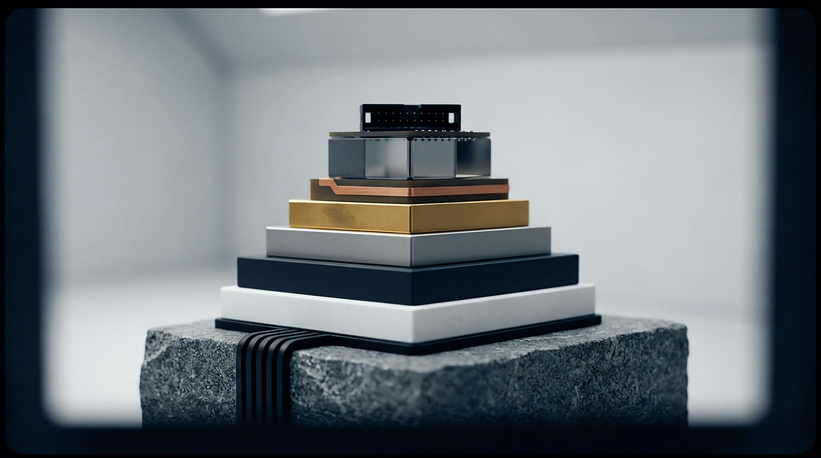
Base metallurgy dictates whether a mold survives repeated freight, humid storage, and millions of clamp cycles. While core and cavity inserts absorb direct injection pressure and abrasive melt, the base plates take the flexing loads. Cutting mold bases from cheap carbon steels like uncertified AISI 1045 or generic Chinese S50C leads to plate deflection, galled guide pins, and rust-choked cooling channels.
Thermal gradients across heavy plate cross-sections aggravate structural deflection.
Pre-hardened tool steels are the bare minimum for tools meant to travel. European DIN 1.2311 and its free-machining sulfurized equivalent DIN 1.2312 maintain 28 to 34 Rockwell C through plates up to 400 millimeters thick. North American practice calls for AISI P20 (UNS T51620) or P20+S for matching strength.
The added sulfur in DIN 1.2312 speeds up pocket roughing and saves cutters, but it leaves an inferior finish and complicates welding if the tool ever needs modification.
Plates cut from pre-hardened 1.2085 stainless steel eliminate cooling passage corrosion during trans-oceanic freight without requiring nickel plating.
Corrosion resistance is equally critical when tools spend weeks in ocean transit or unconditioned warehouses. Humid salt air and temperature swings pit standard cooling passages quickly. Choosing DIN 1.2085 ~ a pre-hardened martensitic stainless containing roughly 12 to 14 percent chromium with sulfur added for machinability ~ gives about 30 Rockwell C hardness without rusting.
Drilled water lines stay clear of scale and oxidation, preserving predictable heat transfer regardless of water quality at the receiving facility.
- AISI P20 Modified Base Plates provide 280 to 320 Brinell hardness across thick sections, preventing plate crushing under clamp tonnages reaching 30 megapascals across parting land areas.
- DIN 1.2085 Corrosion Resistant Plates protect deep cooling passages from oxidation during unheated transit, maintaining bore integrity without chemical passivation treatments.
- Through-Hardened Cavity Sub-Inserts machined from AISI H13 or DIN 1.2344 vacuum-heat-treated to 48 to 52 Rockwell C protect high-wear shut-off angles from progressive rounding.
- High-Tensile Clamping Screws rated to ISO 898-1 Class 12.9 resist bolt stretch caused by continuous cyclic pressure spikes during mold pack phases.
Arguments for substituting standard structural carbon steel assume deflection remains negligible under four hundred tons of machine clamping force, overlooking long-term fatigue in the softer base.

Actuation
External alignment features must register the tool halves before the cavity steel touches. When a mold moves to a different press, variations in platen wear, tie-bar stretch, and moving-platen parallelism inevitably introduce angular error. Bases built without adequate guidance force delicate shut-off faces to take that alignment load, leading to chipped parting edges, galling, and tool damage within the first shift.
Operating temperatures cause steel to expand, quickly absorbing initial running clearances.
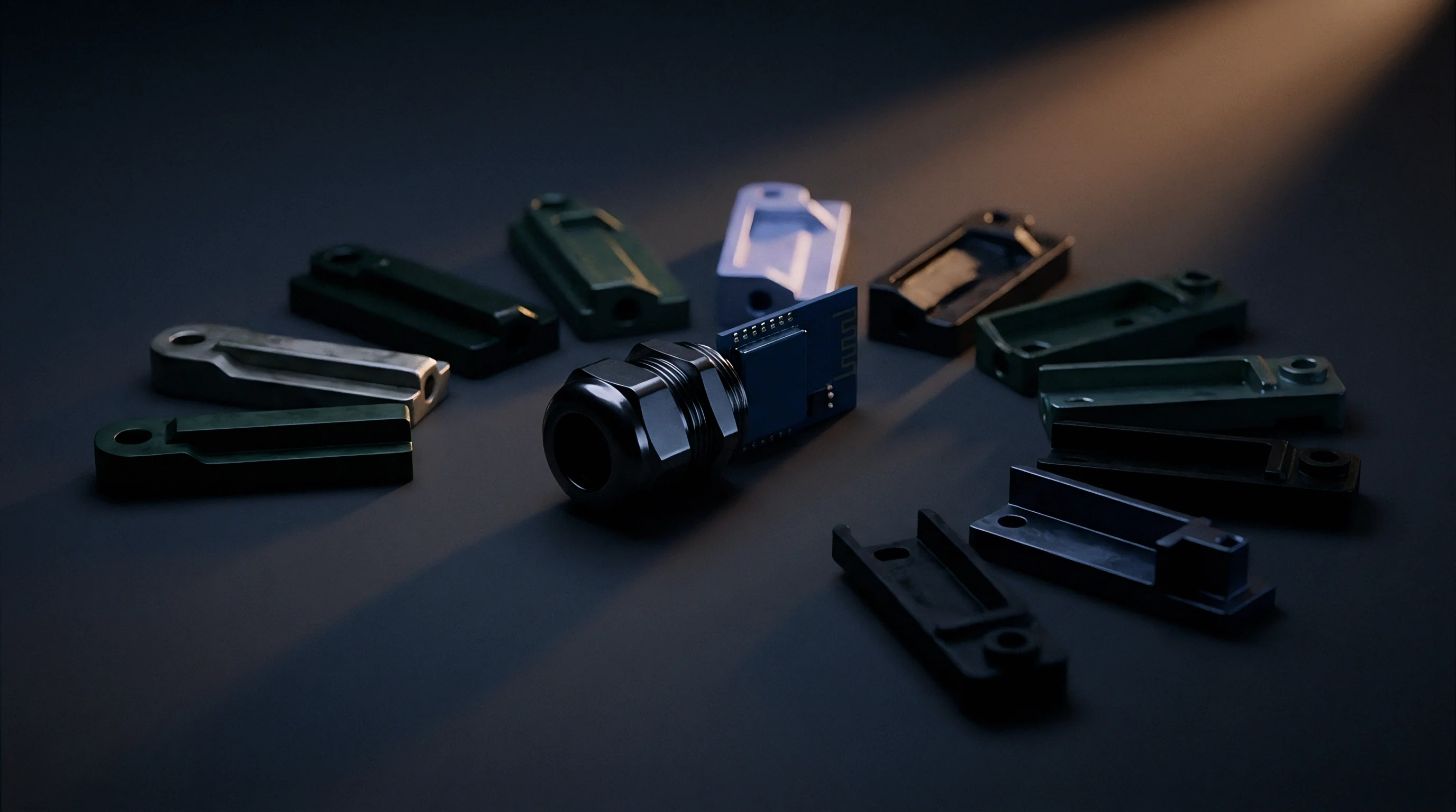
Standard leader pins and bushings provide initial coarse location during mold closing. Transferable tools typically specify Hasco Z01 or DME guide pins made from case-hardened alloy steel (like 1.7131 / AISI 5115) ground to 60 Rockwell C. Guided ejection is just as critical. Instead of letting the ejector plate float on the machine knockout rods, molds built to move use dedicated guide pins running in bronze bushings plugged with solid graphite.
That keeps the plate from racking and binding when parts eject unevenly.
Why Do Guided Ejection Systems Prevent Plate Binding?
Ejection forces are rarely balanced across a wide plate, especially with deep ribs or uneven part features. In an unguided setup, off-center resistance cocks the ejector assembly, jamming the pin shanks against their clearance holes in the B-plate. Guiding the assembly along hardened pillars anchored directly to the back clamping plate keeps the travel square and stops pins from binding in their bores.
Cams, slides, and lifters require standard off-the-shelf retainers and position locks. Any slide moving perpendicular to the draw needs positive retention during transit and cycling. Specifying catalog locks (such as Hasco Z181 or Superior Slide Locks) means a maintenance shop can pull replacement springs, detents, or wear plates from local inventory instead of machining custom parts on a mill.
Proving out mechanical systems before shipment requires a methodical checklist:
- Verify leader pin engagement occurs at least 15 millimeters before any core or cavity steel makes contact along the parting line.
- Confirm ejector half stroke travel reaches positive mechanical stop buttons without bottoming out against the back clamping plate.
- Check slide stroke clearance against catalog detent retention limits to prevent slide drop during crane maneuvering.
- Inspect self-lubricating bronze wear plates for minimum 0.05-millimeter proud clearance above parent plate pockets.
- Validate hydraulic core-pull couplings against ISO 16028 quick-action hydraulic disconnect standards.
Maintaining tight side-interlock alignment remains difficult when platen temperatures fluctuate between seasonal shop extremes.
Title
Physical interchangeability matters little if legal ownership and digital engineering records remain unsettled. Specifying catalog steel and standard fittings helps no one if the original vendor withholds parametric 3D models, CNC toolpaths, or the native bill of materials. Purchase contracts need to tie final non-recurring engineering payments directly to the delivery of both the physical mold and its complete digital data package.
Production prints rarely reflect modifications made during bench tuning.
A complete data handover includes unlocked 3D assemblies in neutral formats (STEP AP214 or Parasolid XT) alongside the native CAD files (Siemens NX, Creo, or SolidWorks). Every detail in the assembly tree needs an explicit catalog number referencing a standard supplier. If a mold builder turns custom leader pins or grinds lifters by hand without updating the prints, the receiving shop has to reverse-engineer basic wear parts during routine maintenance.
Tooling contracts withholding final payment until delivery of 3D CAD models matching CMM coordinate inspection reports prevent post-transfer machining disputes.
Clear legal title is essential before pulling a tool. Foreign molders sometimes assert commercial liens or claim co-ownership of venting and runner geometry when a client attempts to relocate tooling. Sourcing agreements must state unequivocally that the buyer holds sole, unencumbered title to the base, cavity inserts, manifolds, and sub-assemblies from the moment chips fly.
Physical metal tags stamped with the buyer’s asset identification number, mold serial code, and base standard classification must be riveted directly to the non-operator side of the clamping plate.
A tool built around proprietary, non-standard base dimensions leaves the buyer permanently tied to the original molding shop.