Substrate Permittivity Thermal Drift in Microwave Printed Circuits
Thermal substrate drift detunes microwave filters and transmission lines, driving radiated emissions past regulatory limits during compliance sweeps.

Resin
When thermal conditions change in microwave substrate laminates, the dielectric matrix undergoes physical shifts that alter its relative permittivity. This drift is governed by the dielectric constant’s temperature coefficient, designated as TCDk. At high microwave frequencies, even minor permittivity changes alter trace electrical length, shift characteristic impedance, and pull circuit resonant frequencies off target.
By the time energy moves through an RF assembly, dielectric drift inside the board can already compromise tuning before signals ever reach the antenna terminal.
The polymer matrices used in RF laminates change polarizability with temperature. As heat rises, thermal expansion increases molecular volume, which lowers the density of polarizable dipoles per unit volume and pushes relative permittivity down. Phase transitions in the polymer can also abruptly change the direction of this thermal slope.
Polytetrafluoroethylene, for instance, undergoes a first-order crystalline phase transition near nineteen degrees Celsius. This structural shift within the fluoropolymer matrix flips the temperature coefficient of permittivity from negative to positive right in the middle of normal operating temperatures.
Dielectric constant thermal coefficients in fluoropolymer laminates swing from negative to positive values near eighteen degrees Celsius due to crystalline phase transitions.
Hydrocarbon thermoset materials show much more linear dielectric thermal curves than unreinforced fluoropolymers. Formulators stabilize thermal expansion and offset negative polymer TCDk slopes by loading the resin with functional ceramic fillers like titanium dioxide and silica nanoparticles, which carry positive temperature coefficients of permittivity. Blending these ceramic particulates into the matrix counteracts the base polymer’s negative coefficient, bringing dielectric stability close to zero parts per million per degree Celsius across industrial temperature ranges.
Reinforcing structures add mechanical constraints that reshape volumetric expansion. Continuous glass fabrics hold in-plane dimensions stable while forcing thermal expansion out along the perpendicular thickness axis. Absorbed moisture complicates behavior even further, as water has a relative permittivity near seventy-eight at room temperature.
When ambient humidity drives water molecules into the matrix, the added polarizability and higher loss tangent destabilize dielectric properties during thermal sweeps.
- Fluoropolymer phase shift alters molecular packing density near room temperature, causing non-linear permittivity variations across standard operating ranges.
- Ceramic filler loading counteracts resin expansion by introducing inorganic materials that carry positive permittivity temperature coefficients.
- Glass weave geometry restricts lateral expansion under heat, concentrating dimensional movement along the thickness axis.
- Water molecule absorption raises the effective dielectric constant and dissipation factor whenever thermal stress forces humidity into resin void spaces.
Evaluating substrate options requires looking across the entire operating thermal envelope rather than relying on a single baseline measurement at room temperature.
Trace
Dielectric drift directly degrades printed transmission line performance across microwave bands. Microstrip and stripline traces rely on relative permittivity to establish both characteristic impedance and propagation velocity. When the dielectric constant drops, phase velocity speeds up while line impedance rises past nominal design targets.
That higher impedance creates reflections at component interfaces, driving up voltage standing wave ratio and cutting power transfer efficiency through output matching networks.
Narrowband resonant circuits are particularly vulnerable to thermal permittivity movement. Microstrip bandpass filters, hairpin resonators, and coupled-line structures shift center frequencies in proportion to the square root of the dielectric change. Under heat, a negative TCDk forces these resonant frequencies upward.
As center frequencies drift, band-edge attenuation boundaries slide with them, which can spill energy outside assigned channels or attenuate the carrier inside the intended passband.
Planar antenna arrays run into beam-steering errors and impedance mismatches under thermal stress. When microstrip patch elements tuned for tight channels drift off resonance during transmit sweeps, degraded return loss reflects power back into the power amplifier stage. This extra load increases heat dissipation in active RF components and accelerates circuit wear over time.
Narrowband microstrip bandpass filters engineered without thermal permittivity compensation push carrier sidebands past regulatory spectral masks during cold start cycles.
Radiated emission failures often happen when substrate drift slides spurious frequencies into restricted bands during compliance testing. Environmental test chambers push equipment across operating ranges from minus forty to plus eighty-five degrees Celsius. Radiated power levels that comfortably meet spectral masks at room temperature can breach limits when permittivity drift pulls filter poles out of alignment during extreme thermal sweeps.
| Substrate Chemistry | Dielectric Constant at 10 GHz | TCDk Value Range (ppm/deg C) | Resonant Shift at 10 GHz (MHz) | Emission Margin Erosion |
|---|---|---|---|---|
| 2.17 to 2.50 | -160 to -220 | +8.0 to +11.0 | Severe | |
| 3.00 to 10.20 | -50 to +50 | -2.5 to +2.5 | Low | |
| 3.38 to 3.55 | +30 to +60 | -1.5 to -3.0 | Moderate | |
| 4.20 to 4.60 | +150 to +350 | -7.5 to -17.5 | Critical |
Ignoring thermal substrate drift during initial RF layout leads to expensive board re-spins and forces repeated compliance chamber runs late in development.

Bench
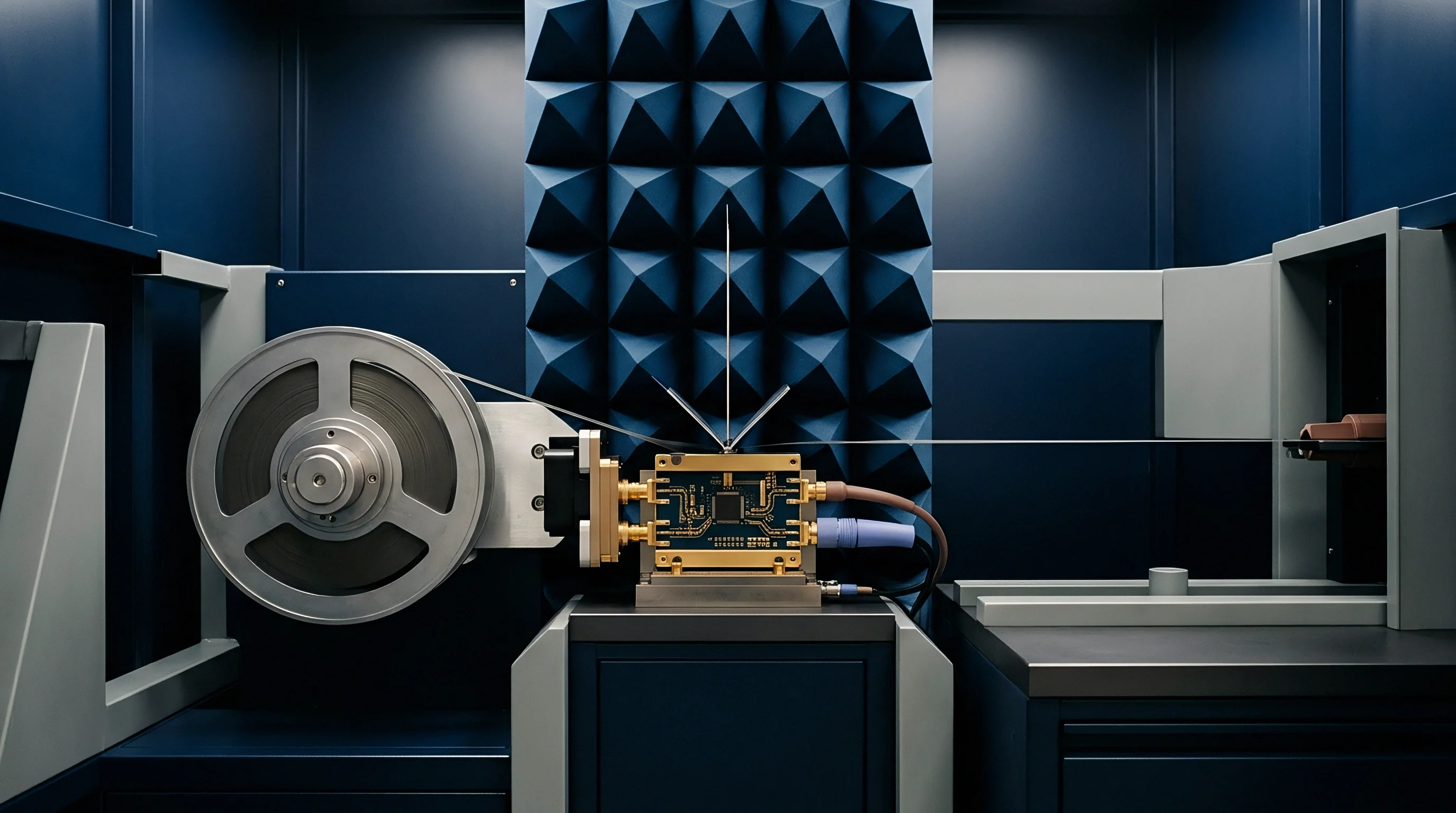
Measuring dielectric thermal drift accurately demands specialized fixtures and calibrated RF instrumentation. Split-post dielectric resonators measure the complex permittivity of bare sheet materials without requiring metal plating. Placed inside an environmental chamber, the cavity tracks dielectric constant shifts as air temperature moves through specified test limits, while an RF network analyzer monitors shifts in peak resonance frequency and quality factor to calculate relative permittivity and loss tangent together.

How Do Split Post Resonators Isolate Dielectric Drift?
Resonator fixtures isolate substrate behavior by decoupling conductor losses from underlying dielectric changes. Transverse electric field modes in the cavity interact directly with the bare laminate sample. Without metallic traces on the test piece, copper surface roughness and trace etching variations cannot distort the extracted permittivity data.
Calibrating the fixture requires running baseline empty-cavity measurements over the target temperature range to subtract the thermal expansion of the aluminum or copper cavity walls.
Coaxial test cables and interconnects introduce phase drift inside test chambers during thermal sweeps. Cable dielectrics expand under heat, shifting phase length and creating insertion loss variations that obscure the substrate’s true response. High-precision testing requires phase-stable cables with phase-tracking fluoropolymer or silicon dioxide insulation, as well as full vector network analyzer calibrations performed at thermal equilibrium for every temperature step.
- Position unclad substrate sample inside split-post dielectric resonator fixture within environmental test chamber.
- Connect phase-stable microwave cables through chamber port walls to high-precision vector network analyzer.
- Stabilize chamber at initial baseline temperature point for sixty minutes to eliminate thermal gradients across sample depth.
- Record TE010 resonance frequency peak and 3 dB bandwidth points using network analyzer trace markers.
- Ramp chamber temperature at controlled rate not exceeding two degrees Celsius per minute toward next plateau.
- Hold target temperature plateau for thirty minutes before capturing secondary resonance transmission data.
- Calculate relative permittivity and loss tangent at each temperature node using fixture extraction algorithms.
Substrate vendors frequently publish single-frequency permittivity ratings at room temperature while omitting negative drift coefficients measured across wider thermal ranges.

Foil
Copper foil surface profiles directly alter the effective dielectric constant seen by microwave transmission lines. Electrodeposited copper has microscopic peaks and valleys that extend into the polymer matrix. At microwave frequencies, current concentrates within a thin skin depth along this conductor-substrate interface.
Rough copper increases the physical path length of high-frequency current, slowing wave propagation and raising the effective relative permittivity above what smooth dielectric materials report.
Mismatched thermal expansion between metal foil and polymer substrate generates mechanical stress along trace interfaces. Copper carries a thermal expansion coefficient near seventeen parts per million per degree Celsius, whereas unreinforced dielectric materials expand rapidly along the thickness axis above their glass transition temperature. This anisotropic movement pulls micro-textured copper away from the matrix, altering the micro-fill factor at the boundary and driving baseline permittivity drift over extended thermal cycling.
Specification limits under IPC 4103 mandate dielectric tolerance reporting across operational thermal boundaries to prevent host integration failure.
Moisture tends to accumulate where micro-voids form along the conductor-dielectric interface. Thermal cycling draws ambient water vapor into these untreated boundaries, elevating dielectric losses and distorting local permittivity along high-speed signal paths. Using smooth, low-profile treatments like Very Low Profile or Hyper Very Low Profile foils reduces surface field enhancement while minimizing moisture retention at the interface.
Questions remain about long-term microstrip phase velocity stability in outdoor automotive radar, largely due to uncertainty over how mechanical stress builds up at low-profile foil interfaces over time.

Paperwork
Regulatory type approvals require radio products to demonstrate compliance across their full operating temperature range. The European Telecommunications Standards Institute mandates radiated emission and receiver sensitivity testing under extreme thermal conditions in standards like ETSI EN 300 328 and EN 301 893. If dielectric drift detunes internal filter circuits during hot or cold chamber sweeps, spurious emissions can exceed allowable limits and block market clearance.
A four megahertz frequency shift on a five gigahertz center frequency triggers non-compliance during ETSI EN 300 328 spurious emission scans at high thermal limits.
Federal Communications Commission modular approvals hold host integrators strictly to the original reference layout. Changing board laminates to fix unexpected thermal drift invalidates an existing modular grant if trace geometry or dielectric constants exceed permissive change tolerances. Filing a Class II permissive change requires new chamber test reports, filing fees, and administrative reviews that can delay product launches by six to twelve weeks.
| Regulatory Authority | Applicable Standard | Thermal Test Scope | Failure Mode Driver | Approval Filing Impact |
|---|---|---|---|---|
Procurement specifications for RF circuit boards need to establish tight dielectric thermal stability requirements alongside standard IPC manufacturing rules. Purchase orders referencing IPC-4103 should explicitly mandate TCDk limits across the equipment’s full operating range. Relying solely on ambient dielectric constant ratings leaves host hardware exposed to yield losses and performance drops in the field.
- Specification limits require explicit TCDk ceiling values in parts per million per degree Celsius across the entire operating range.
- Vendor lot validation relies on material batch certificates to verify dielectric constant variation at high and low temperature extremes.
- Host re-certification plans set aside budget for secondary chamber testing whenever laminate dielectric chemistry changes mid-production.
- Permissive change filings weigh trace geometry adjustments against regulatory limits when correcting thermally induced frequency drift.
Adding compliance clauses to procurement contracts ensures dielectric tolerances are verified on raw laminate shipments before PCB fabrication starts.