Meaning
A radio frequency instrument measures complex impedance and transmission characteristics by generating a stimulus signal and analyzing the resulting phase and magnitude of the wave. The vector network analyzer determines how components or systems handle electrical energy across a specified frequency range. It characterizes passive and active devices through the acquisition of scattering parameters that map the flow of electromagnetic power.
These measurements provide data on return loss and insertion gain. Boundary conditions depend on the calibration process, which removes systematic errors from the measurement environment to ensure data accuracy.
Signal Dynamics
Calibration standards permit this equipment to shift the measurement reference plane to the physical interface of the test subject. Practitioners use short, open, load, and thru artifacts to establish a mathematical baseline for the system. Once these error terms sit stored in the memory, the device computes the corrected performance of the component under test.
Frequency domain analysis allows the detection of small impedance mismatches that time domain reflectometry might obscure.
Integration Procedures
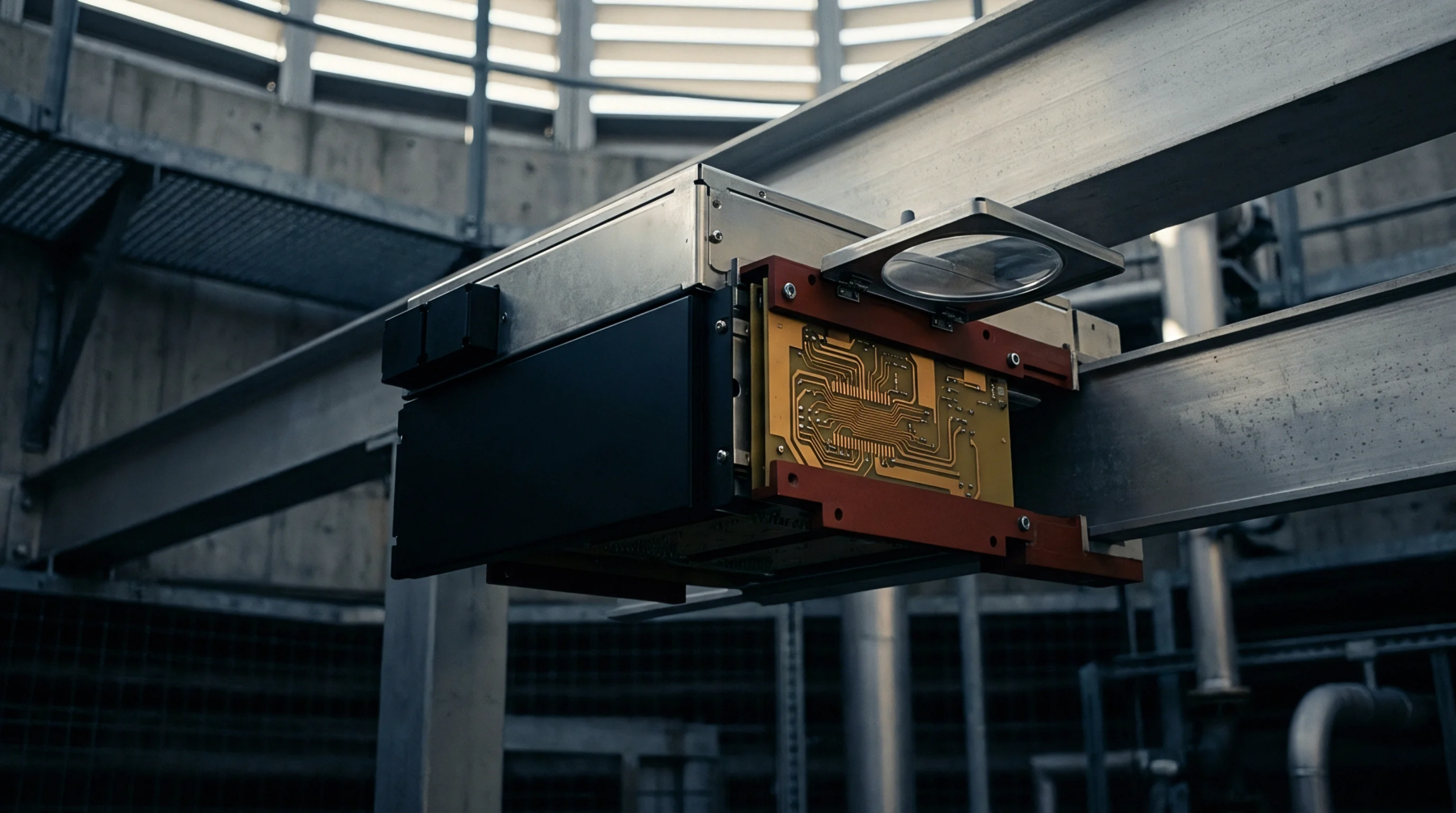
Reliability testing in high volume production environments relies on accurate performance mapping of radio frequency modules. Assemblies undergo connection to this tool during the final verification stage of the assembly line to confirm compliance with hardware specifications. Technicians observe the frequency response curves while manipulating the physical layout of the module to optimize signal path integrity.
The software suite extracts the relevant transmission data directly into the acceptance report. Any drift in the measured scattering parameters beyond the tolerance band necessitates an immediate audit of the probe interface or the cabling.
Hardware Performance
Measurement precision rests on the stability of the internal local oscillators and the quality of the directional couplers. Internal processors calculate the vector ratios between the transmitted and reflected signals to derive the complex coefficients. These values define the relationship between the incident wave and the scattered wave at each port.
A high dynamic range allows the detection of low level leakage signals in deeply buried circuit paths. Improved shielding of the measurement enclosure reduces external interference and provides a stable environment for the analysis of high frequency characteristics.