Meaning
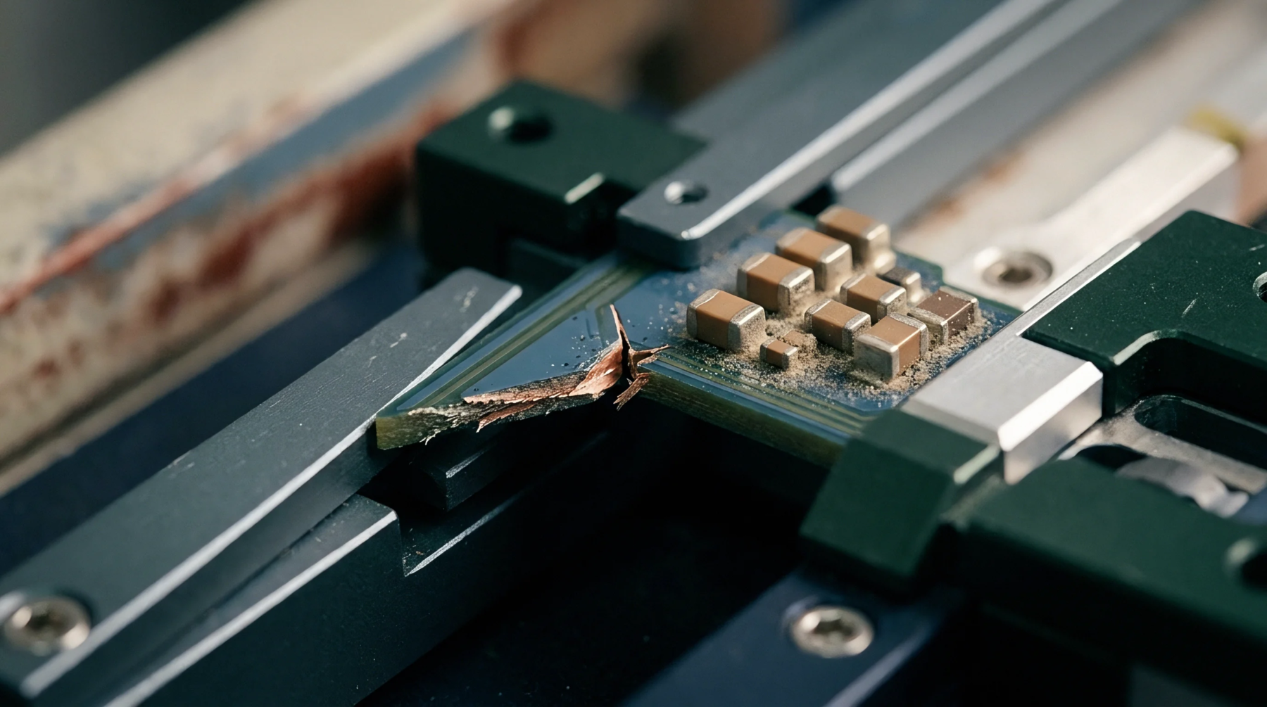
Mechanical behavior in materials with three mutually perpendicular planes of symmetry defines the response of a substance to applied loads where orthotropic elasticity governs internal stress distribution. Anisotropic behavior arises because properties such as Young modulus or Poisson ratio vary depending on the orientation relative to the primary axes of the material architecture. Manufacturers characterize these substances by providing nine independent elastic constants to describe the full stiffness matrix.
Engineers apply this model to predict deformation in layered composites or timber components before production starts.
Structural Variance
Directional stiffness allows designers to tune component performance by aligning high modulus axes with anticipated load paths. Such a strategy reduces material mass while maintaining the integrity of the enclosure under operational strain. Thermal expansion coefficients follow this same directional pattern and create internal tension when the temperature cycles across the assembly.
Practitioners verify that calculated deformation matches the physical test results to confirm the validity of the chosen coordinate system.
Integration Requirement
Hardware specifications mandate an accurate alignment of the material orientation with the global reference frame of the product CAD model. Any rotation of the ply stack during the manufacturing process alters the stiffness tensor and shifts the resonance frequency of the entire module. Integrators verify these angles through microscopic cross-section analysis or ultrasonic inspection during the quality audit of the incoming batch.
Correct positioning avoids unexpected structural failure in the final enclosure when the assembly experiences vibration or impact.
Load Prediction
Finite element analysis depends on precise input values to resolve how orthotropic elasticity modifies the strain energy within a housing or printed circuit board support. Software tools process these stiffness variables to identify potential fracture points before the first prototype undergoes physical testing. Calculations demonstrate that ignoring the cross-coupling between normal and shear stresses leads to inaccurate deflection estimates.
Accurate numerical modeling relies on the strict adherence of the material property data to the specified orientation of the composite fibers.