Cyclic Mechanical Stress Effect on D Band Flange Intermodulation Drift
Cyclic mechanical stress on D-band waveguide flanges causes micro-fretting and torque loss, raising intermodulation distortion and degrading high-order QAM links.

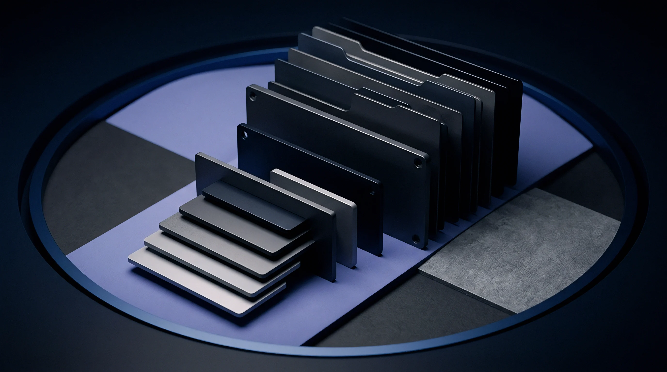
Junction
Metal waveguide interfaces operating at sub-millimeter wavelengths rely on sub-micron surface contact area to maintain continuous ground paths for high-frequency electromagnetic fields. In the D-band allocation spanning 110 GHz to 170 GHz, signal wavelengths shrink to between 1.76 mm and 2.72 mm. At these dimensions, skin depth in standard waveguide metals drops below two hundred nanometers.
Electric current traverses a shallow metal layer right along the mating surface, making the electrical integrity of the joint sensitive to microscopic mechanical interface variations.
Flange interfaces engineered to standard specifications such as IEEE 1785.2 or modified UG-387 configurations rely on metal-to-metal clamping force to establish low-resistance contact. Surface asperities, microscopic peaks created during precision CNC machining or diamond turning, collapse under initial bolt pre-load while surface oxides fracture. This mechanical collapse creates a network of localized conductive spots surrounded by micro-gaps filled with ambient air, moisture, or native oxides, causing interfacial current density to spike dramatically across these constricted points of contact.

Asperity Contact and Nonlinear Conduction Pathways
Microscopic peaks on machined metal mating surfaces dictate the real area of conductive touch between two clamped waveguide structures. While the nominal surface area of a standard WR-6 flange measures several square millimeters, the actual metallic contact area accounts for less than two percent of the total interface surface under normal clamping pressure. Current density through these isolated micro-contacts rises by orders of magnitude relative to the bulk conductor current density.
When high-frequency currents pass through thin oxide layers surrounding these micro-contacts, nonlinear conduction mechanics take over. Electron tunneling occurs through thin ambient dielectric barriers, while thermionic emission operates across thicker oxide regions. These mechanisms introduce nonlinear voltage-current relationships directly into the RF signal path.
When multiple carrier signals propagate across this non-linear mechanical interface, higher-order intermodulation products generate within the joint itself, producing passive intermodulation drift.
| Flange Surface Finish | RMS Roughness (nm) | Effective Contact Area (%) | Skin Depth at 140 GHz (nm) | Initial PIM3 Floor (dBm) |
|---|---|---|---|---|
| Bare Oxygen-Free Copper | 120 | 1.8 | 176 | -118 |
| Direct Electroplated Silver | 85 | 2.4 | 170 | -124 |
| Electroless Nickel Immersion Gold | 210 | 0.9 | 280 | -104 |
| Diamond-Turned Brass | 45 | 4.1 | 215 | -128 |

Waveguide Boundary Conditions at Sub-Terahertz Frequencies
High frequency RF signals flowing through WR-6 metallic conduits generate skin-depth current layers measuring under two hundred nanometers in thickness. Boundary condition discontinuities arise whenever the mechanical joint disrupts the continuous flow of longitudinal wall currents. In D-band systems, physical misalignments as small as five micrometers cause measurable phase shifts and local field enhancements along the flange aperture seam.
Ground contact non-linearities at sub-millimeter interfaces rise sharply whenever surface RMS roughness exceeds ten percent of the skin depth.
High localized electric field intensity inside microscopic interface gaps accelerates non-linear phenomena. Ambient humidity trapped inside non-hermetic flange cavities forms thin moisture films that accelerate micro-galvanic oxidation. As the oxide layer thickens, the tunneling barrier width increases, altering the non-linear conductance profile of the junction.
Flange surface treatments with softer outer metals maintain lower intermodulation distortion over extended operational exposure than high-hardness protective plating.


Vibration
Wind-induced structural deflection on millimeter-wave tower mounts transmits low-frequency physical oscillation into the rigid waveguide interfaces of high-capacity radios. Dynamic bending moments travel down the antenna feed line directly to the D-band flange joint. These external forces superimpose cyclic tensile and compressive stresses upon the static pre-load established by the flange fasteners during installation.
Microscopic displacement occurs across the mating plane as cyclic mechanical stress overcomes local static friction. This phenomenon, known as micro-fretting, continuously alters the geometry and pressure distribution of the contacting asperities. As the physical contact network shifts under dynamic load, the composite electrical resistance of the flange interface varies continuously over time, causing dynamic modulation of the passing RF carrier signals.

Micro-Fretting and Contact Resistance Modulation
Cyclic relative motion between clamped metal faces creates repetitive rubbing at localized touching points. Motion amplitudes as small as fifty nanometers suffice to strip protective surface films, exposing fresh base metal to atmospheric oxygen. The resulting oxidized metal debris accumulates inside the interface micro-gaps as highly resistive particulate matter.
Particulate accumulation alters the local current distribution across the waveguide flange seam. Current pathways constantly break and reform as vibration continues, creating temporal variance in contact resistance that modulates both the phase and amplitude of sub-THz signals passing through the joint, manifesting as intermodulation sidebands that drift in frequency and magnitude alongside the external vibration spectrum.

Why Does Dynamic Structural Displacement Accelerate Intermodulation Drift?
Mechanical movement shifts the physical contact points across oxidized surface asperities millions of times per day. Every cycle of mechanical movement forces the RF current path to navigate a continually changing matrix of nonlinear tunneling barriers and variable contact resistances. The intermodulation distortion spectrum broadens as dynamic micro-displacement continues, elevating the noise floor across adjacent signal channels.
- Surface Oxide Fragmentation exposes unpassivated metal surfaces to immediate oxidation, shifting junction non-linearity parameters during dynamic mechanical loading.
- Micro-Gap Cavity Resonance alters local field distribution when physical vibration changes micro-gap dimensions within the millimeter-wave current path.
- Fastener Clamping Force Relaxation reduces static compressive load, allowing larger shear displacements across the waveguide mating plane under wind stress.
- Galvanic Interface Degradation accelerates material transfer across dissimilar metal interfaces subjected to continuous mechanical oscillation and moisture ingress.
Passive intermodulation levels at 140 GHz drift upward by 18 dB after ten thousand stress cycles when flange bolt pre-load drops below sixty percent of rated torque.
Mechanical stress cycles also induce localized elastic and plastic deformation at the tips of surface asperities. Work hardening occurs in the contact zones, reducing the metal’s ability to conform under pressure and permanently degrading the electrical consistency of the joint. Unmonitored cyclic deflection across high-frequency interfaces degrades backhaul signal clarity, eventually causing link modulation drops that choke network carrier throughput across connected sector sites.


Distortion
Non-linear current density profiles generated across degraded mechanical joints produce unexpected spectral mixing products when high-power carrier signals traverse the waveguide boundary. In high-capacity D-band point-to-point radios transmitting two or more closely spaced carrier frequencies, these non-linearities generate third-order intermodulation products (PIM3) and fifth-order intermodulation products (PIM5) directly inside the transmission line.
Third-order products falling within the receiver passband degrade the signal-to-noise-and-interference ratio of the link. In systems employing complex modulation formats such as 1024-QAM or 4096-QAM, elevated intermodulation distortion compresses the receiver’s available error vector magnitude floor. The extra intermodulation energy acts as a co-channel interference source that cannot be removed by digital signal processing or adaptive equalization.

Intermodulation Spectra and Link Margin Degradation
Mixing products generated inside high-frequency transmission boundaries fold directly into adjacent receiver channels. The relationship between carrier input power and generated third-order intermodulation power follows a non-linear trajectory, where a 1 dB increase in fundamental carrier power typically yields a 3 dB increase in intermodulation product power under ideal junction conditions. Corroded or vibration-damaged flanges deviate from this classical slope, exhibiting unpredictable power-dependent intermodulation spikes.
| Stress Cycles (0.5 mm Deflection) | Carrier Power per Tone (dBm) | PIM3 Level (dBm) | Receiver EVM Floor (%) | Max Supported QAM Format |
|---|---|---|---|---|
| 0 (As Mated) | +18 | -112 | 0.35 | 4096-QAM |
| 1,000 | +18 | -104 | 0.62 | 2048-QAM |
| 5,000 | +18 | -93 | 1.45 | 1024-QAM |
| 10,000 | +18 | -81 | 3.10 | 256-QAM |
| 25,000 | +18 | -68 | 7.80 | 64-QAM |
Intermodulation product magnitude varies dynamically as cyclic stress continues to alter interface geometry. This time-varying distortion causes sporadic frame loss, uncorrectable forward error correction blocks, and automatic modulation fallback to lower-order QAM profiles. The network loses carrier capacity precisely when environmental stress, such as high wind speeds, reaches its maximum.
Standard IEEE 1785.1 specifies an insertion loss variation limit of zero point two decibels across mated sub-terahertz flange joints to maintain system linearity.
Field data confirms that passive intermodulation drift follows a logarithmic progression relative to mechanical stress cycle count. Initial degradation occurs rapidly as surface asperities settle and local oxide barriers break down. Factory-calibrated flange sealants are intended to limit intermodulation drift, operating on the premise that field degradation stems from improper installation torque as well as structural contact dynamics.


Fastener
Maintaining repeatable interface compression on WR-6 waveguide joints requires careful selection of threaded hardware and load-retaining spring washers. Standard stainless steel four-bolt configurations used in legacy UG-387 flange patterns often fail to maintain consistent axial tension when subjected to thermal cycling and wind stress.
Differential thermal expansion between aluminum radio housings, brass or copper waveguide flanges, and steel fastening hardware causes substantial clamp force variation across operational temperature ranges spanning minus forty to plus eighty-five degrees Celsius. As temperature drops, steel fasteners contract at a lower rate than aluminum housings, reducing overall interface compression. Subsequent mechanical vibration accelerates thread back-off, allowing micro-gaps to expand.

Torque Loss Mitigation and Mechanical Retention Strategies
Threaded connections experience gradual pre-load decay under continuous thermal expansion and structural flexure. Precision mechanical retention methods use conical spring washers, also known as Belleville washers, arranged in series or parallel stacks to maintain continuous axial force on the waveguide flange seam despite thermal and mechanical displacement.
- Clean all flange mating surfaces using high-purity isopropyl alcohol and lint-free wipes to remove organic contaminants.
- Inspect alignment pin sleeves and locating holes under magnification to verify freedom from burrs or metal debris.
- Apply specified anti-seize compound exclusively to bolt threads while keeping the waveguide aperture completely clean.
- Torque opposing diagonal bolts in alternating stages to twenty percent, sixty percent, and finally one hundred percent of target torque.
- Install pre-loaded Belleville conical spring washers to maintain continuous axial tension during thermal expansion and mechanical flexing.
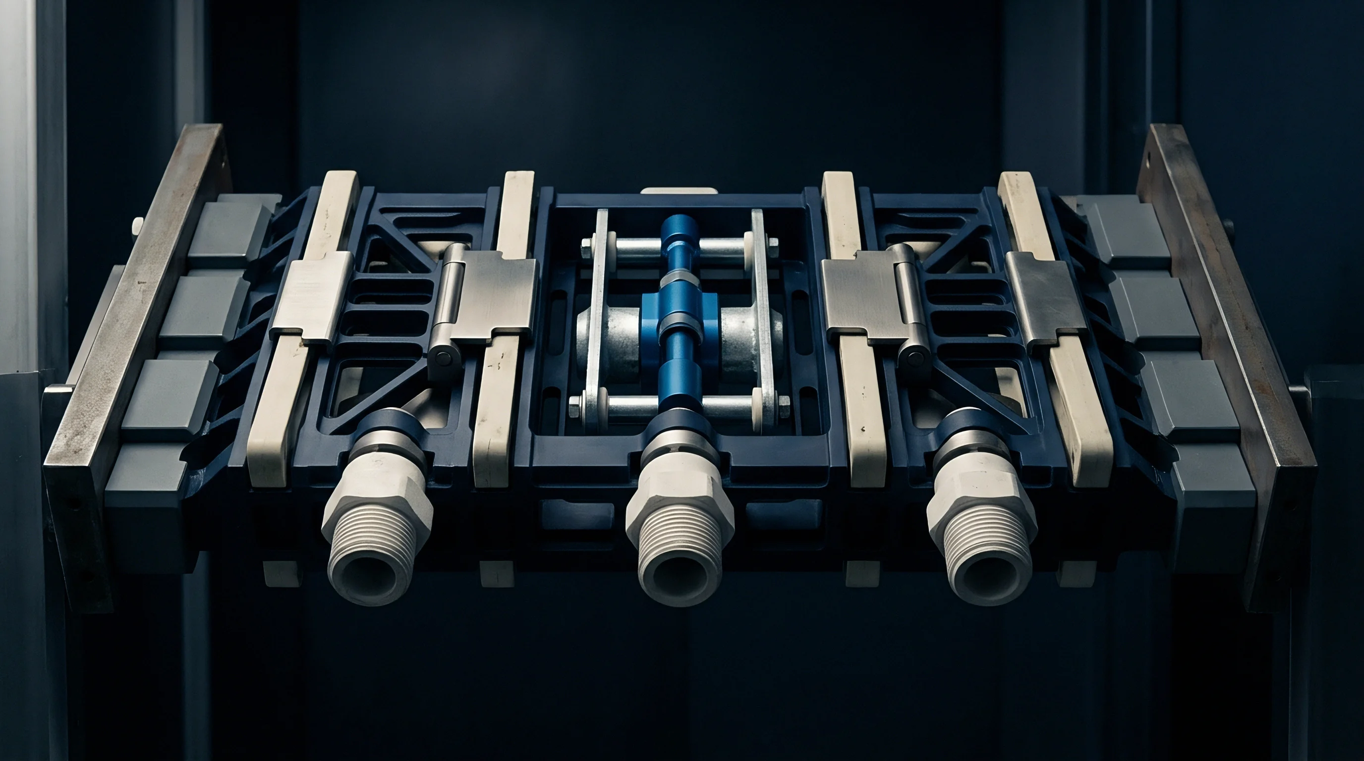
Precision Alignment Pin Dynamics
Locating hardware maintains shear alignment across opposing waveguide apertures to prevent step discontinuities in the interior walls. Standard sub-THz precision flanges utilize hardened dowel pins paired with tight-tolerance reamed holes. Precision alignment minimizes shear movement along the primary contact plane, isolating the electrical junction from side-load stresses induced by tower movement.
Spring-loaded strain retention washers cushion flange interfaces against torque decay caused by differential thermal expansion across dissimilar metals.
Selecting fasteners with thermal expansion coefficients matched closely to the flange material reduces clamp force fluctuations. Titanium grade 5 bolts paired with brass flanges offer superior thermal matching relative to standard 316 stainless steel hardware. Telecom procurement specification clause RF-704 mandates that installed outdoor microwave links maintain intermodulation levels below minus one hundred and ten decibels relative to carrier under wind speeds up to forty meters per second.

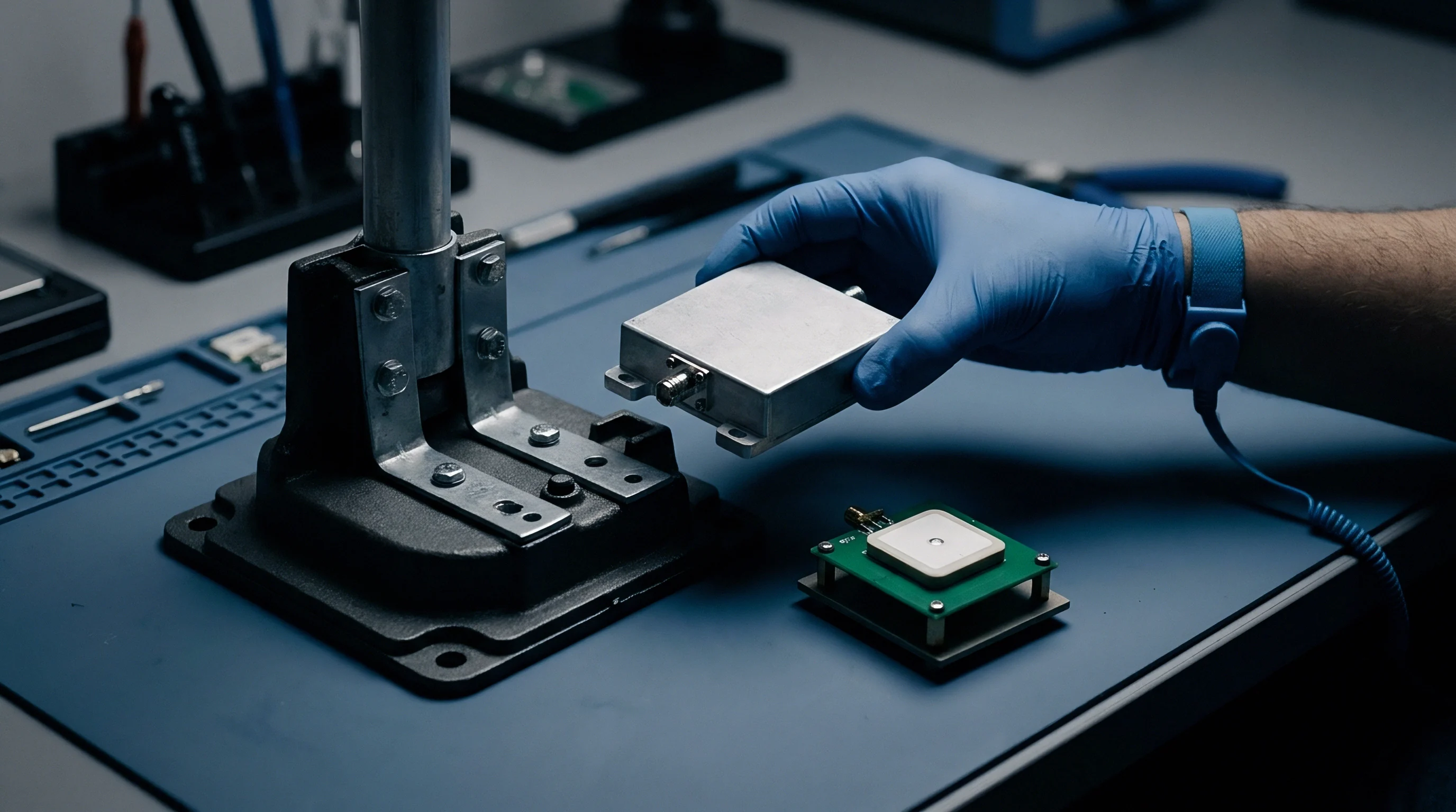
Screening
Verifying sub-THz flange stability prior to tower mounting demands targeted physical oscillation profiles paired with real-time spectrum monitoring. Conventional factory quality checks rely solely on static insertion loss measurements at room temperature, which fail to reveal intermodulation non-linearities that emerge only when the joint experiences dynamic physical stress.
A complete environmental screening protocol subjects the candidate waveguide assembly to simultaneous mechanical vibration, thermal cycling, and high-power two-tone RF excitation. Real-time intermodulation tracking during dynamic stress exposure reveals micro-fretting degradation within minutes, enabling hardware engineers to reject unstable flange designs prior to deployment.

Bench Test Protocols for Sub-Terahertz Intermodulation
Laboratory verification of passive intermodulation stability utilizes a dual-carrier tone generator coupled to high-dynamic-range spectrum analyzers. Two high-power D-band signals, typically injected at plus eighteen decibels milliwatt per tone, propagate through the test article while an electrodynamic shaker applies controlled vibration across the three orthogonal axes.
- Carrier Power Level Selection sets fundamental tone amplitude to reflect maximum operational transmitter output plus six decibels of test margin.
- Vibration Profile Alignment applies sinusoidal swept vibration between ten and two thousand hertz to simulate structural tower resonances.
- Residual PIM Calibration verifies that test bench couplers, loads, and diplexers contribute intermodulation products below minus one hundred and thirty decibels milliwatt.
- Thermal Cycling Overlay sweeps ambient chamber temperature between minus forty and plus eighty-five degrees Celsius during physical vibration.

Worked Example of D Band Backhaul Link Margin Allocation
Consider a point-to-point backhaul connection operating at one hundred and forty gigahertz over a one point five kilometer path under high rain fade conditions. The system transmitter outputs plus twenty decibels milliwatt combined carrier power into a high-gain parabolic dish antenna with fifty decibels of gain on each end. Free space path loss over one point five kilometers at one hundred and forty gigahertz calculates to one hundred and thirty-nine point two decibels.
Atmospheric gas attenuation adds zero point six decibels, while rain fade margin requires an additional eighteen point five decibels for ninety-nine point nine nine nine percent link availability.
The link budget allocates a base receiver sensitivity floor of minus sixty-two decibels milliwatt for 1024-QAM operation at a ten gigabit per second data rate. Unstressed, freshly installed waveguide flanges exhibit a third-order passive intermodulation level of minus one hundred and twelve decibels milliwatt, sitting fifty decibels below the receiver thermal noise floor.
After three years of field exposure involving two million mechanical stress cycles from wind load, micro-fretting elevates the joint intermodulation floor by thirty-four decibels to minus seventy-eight decibels milliwatt. Concurrently, thermal cycling relaxes bolt torque, adding an extra three decibels of variable contact attenuation. The effective intermodulation energy now sits just sixteen decibels below the fundamental signal level, severely corrupting the outer constellation points of the 1024-QAM grid.
The elevated intermodulation noise floor degrades overall signal-to-interference-plus-noise ratio (SINR) from twenty-eight decibels down to nineteen decibels. This reduction forces the adaptive coding and modulation engine to downshift from 1024-QAM (ten gigabits per second) to 128-QAM (seven gigabits per second) to maintain acceptable frame error rates. The loss of three gigabits per second in net backhaul throughput highlights the direct financial impact of cyclic flange degradation on network capacity.
To prevent unbudgeted link downgrades, system designers add a dedicated seven-decibel intermodulation drift margin into the initial link budget. This margin demands strict quality acceptance standards for installed flange hardware, including mandatory verification of surface roughness, torque locking mechanisms, and environmental seals during factory screening.
System integrators specify complete qualification dossiers for all outdoor millimeter-wave interfaces destined for high-wind tower sites. Hardware designs passing multi-axis vibration testing alongside simultaneous two-tone RF monitoring ensure long-term operational stability, preserving backhaul bandwidth across the entire deployment lifecycle.