Meaning
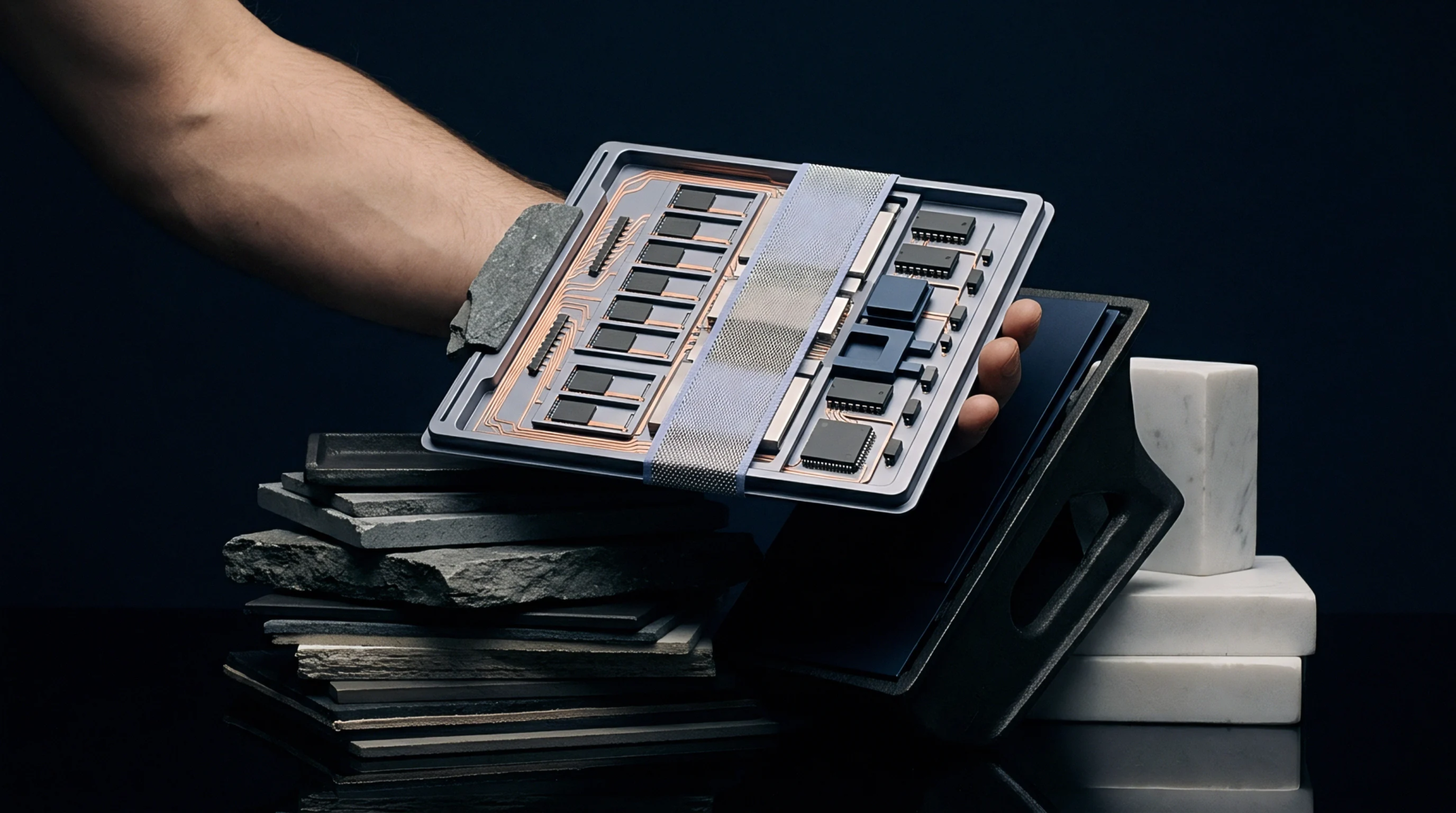
Coordinates representing the exact geometric center and rotation angle of each electronic component on a printed circuit board guide automated assembly equipment. This pick and place centroid dataset allows robotic systems to locate, grasp, and orient surface mount devices accurately during high-speed production. It establishes the mechanical bridge between the digital layout and the physical board.
The boundary of its utility is reached when the physical parts are soldered in the reflow oven.
Data Extraction
Extracting the positional file occurs during the final stages of the circuit board design process. The electronic computer-aided design software generates a text document containing the reference designators, package sizes, and coordinate offsets. This export file is structured as a table that the assembly line software interprets to sequence the robotic arm movements.
Missing or inaccurate columns can lead to offset errors that ruin the entire production run.
Placement Accuracy
Correct alignment of the machine nozzle relies on these spatial markers to execute precise component drops. This step recalculates the relative position of the board to match the coordinate file. Precise coordination prevents short circuits.
Machine Programming
Uploading the layout coordinates to the assembly line software is the final step before initiating production. This software allows technicians to define which machine feeders hold specific reels of components. The technician maps the part numbers to the coordinate table so that each component is fetched from the correct tray or tape feeder.
This digital setup phase ensures the rapid execution of the board stuffing process. It also facilitates the visual inspection of the first completed board before starting high-volume runs.