Meaning
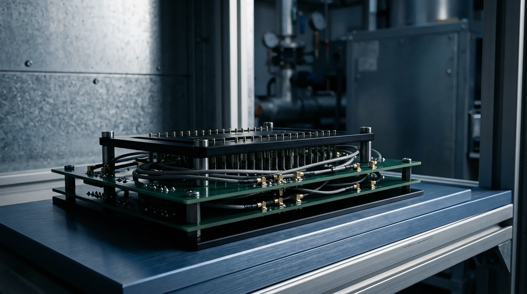
Precision test hardware bridges high-speed printed circuit board traces with measurement instruments to evaluate signal quality. Using a signal integrity fixture allows validation engineers to capture eye diagrams and insertion loss profiles without altering signal path impedance. Custom microstrip launches and low-loss coaxial cables connect physical test points to high-bandwidth oscilloscopes.
The scope covers physical test interface characterization and trace probing, ending where automated soft-error bit rate testing begins.
Impedance Matching
Discontinuities along high-speed signal paths reflect energy, distorting digital pulse transitions. A signal integrity fixture maintains fifty-ohm single-ended or one-hundred-ohm differential target impedance across launch points and test cables. Impedance matching prevents artificial reflections from corrupting real-time oscilloscope measurements during high-speed serial bus validation.
De-Embedding Protocol
Test fixture cables and connectors introduce parasitic inductance and attenuation into measured wave shapes. Calibration of a signal integrity fixture uses 2x Thru or TRL calibration patterns to mathematically remove fixture effects from raw scope captures. De-embedding yields clean waveforms representing true signal quality at silicon transmitter pins.
Interface Boundary
High-density board designs lack room for dedicated SMA connectors near high-speed transceiver packages. Applying a signal integrity fixture requires solder-in probe tips or spring-loaded micro-probes attached directly to board test vias. Physical layout constraints dictate probe tip selection to avoid capacitive loading on high-speed data lines.