Designing Monolithic Titanium Bipod Flexures for Cryogenic Optomechanical Subsystems
Monolithic Ti-6Al-4V ELI bipod flexures isolate cryogenic optical mirrors from thermal deformation when precision wire EDM recast layers are chemically removed.


Frost

Phase Behavior and Yield Characteristics at Four Kelvin
Deep thermal immersion transforms structural metals by altering dislocation dynamics and suppressing atomic slip planes. Grade 23 titanium alloy (Ti-6Al-4V ELI) retains structural ductility down to liquid helium temperatures of 4.2 Kelvin, avoiding the cataclysmic ductile-to-brittle transition common in body-centered cubic ferritic steels. Keeping interstitial oxygen capped at 0.13 percent and iron at 0.25 percent prevents low-temperature embrittlement while raising micro-yield strength.
Room-temperature yield strength sits near 880 MPa, scaling past 1400 MPa when cooled to cryogenic thresholds.
This higher proportional limit expands the elastic energy storage capacity of flexures, permitting wider angular deflection without permanent mechanical deformation. Elastic modulus hardens simultaneously, rising from 114 GPa at 293 Kelvin to approximately 126 GPa at 20 Kelvin. Because of this stiffness increase, structural models built on room-temperature constants underestimate flexure parasitic restoring forces by roughly ten percent once operating at working temperature.
Optomechanical designers adjust spring rate parameters to account for this change when calculating actuator force budgets and system resonance modes.
Titanium Grade 23 maintains a minimum five percent total elongation at 4.2 Kelvin when interstitial oxygen content remains below 0.13 weight percent.
Thermal Contraction Differential and Interfacial Strain
Integrated optical assemblies face severe thermal expansion mismatches between glass substrate mirrors and metal support structures. Fused silica undergoes an integrated thermal contraction of approximately 0.25 mm per meter when cooled from ambient room temperature to 77 Kelvin, whereas silicon carbide contracts by 0.21 mm per meter over the same range. Titanium Grade 23 experiences an integrated contraction of roughly 1.73 mm per meter down to liquid nitrogen cryogenic states, stabilizing near 1.80 mm per meter down to 4.2 Kelvin.
Rigid bolted interfaces transfer this differential shrinkage directly into the optical element, creating astigmatism, surface figure error, and optical axis decentration. Monolithic flexures act as compliance transformers, absorbing bulk structural contraction through elastic blade bending while maintaining precise line-of-sight pointing. Structural geometries that fail to balance radial compliance against axial rigidity distort mirror surfaces beyond acceptable fraction-of-a-wavelength wavefront thresholds under thermal cycling.


Geometry

Blade Kinematics and Parasitic Stiffness Isolation
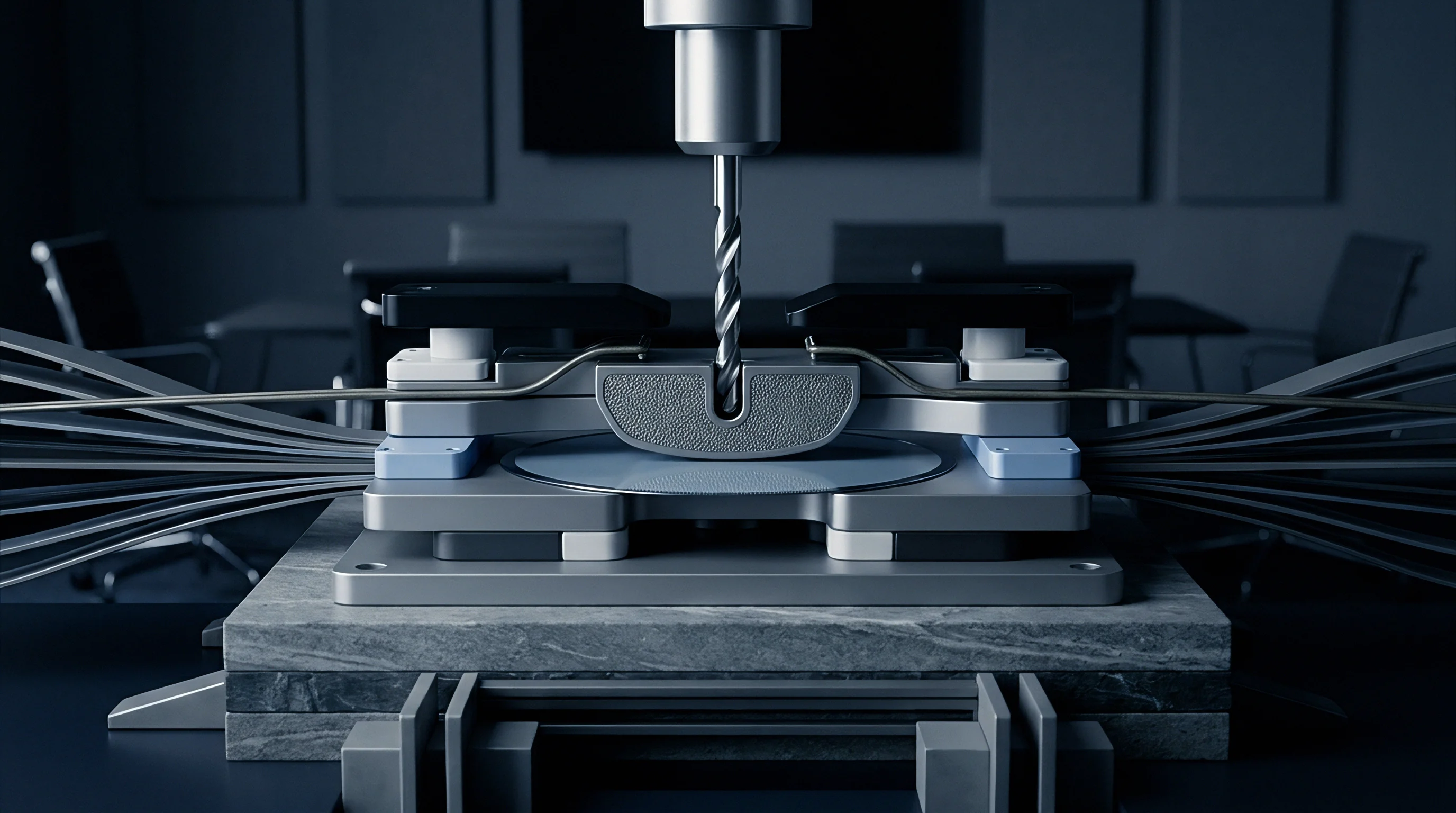
Monolithic bipod flexure assemblies isolate mirror mounts across six mechanical degrees of freedom by deploying paired compliant flexure blades. Each bipod leg operates as a flexible hinge that restricts motion along its longitudinal orientation while yielding along out-of-plane rotational and translational axes. Symmetrical arrangement of three bipod flexure pairs spaced at 120-degree radial increments creates a kinematic coupling scheme.
Radial contraction of the cold bench drives flexure blade bending without imparting bending moments into the optic, preserving optical wavefront quality across extreme thermal excursions.
Flexure leaf thickness dictates the compliance ratio between constrained axes and free rotational axes. Blade thicknesses typically range between 0.3 mm and 0.8 mm depending on mirror mass, maximum shock loading criteria, and allowable parasitic force thresholds. Thinner flexures lower parasitic bending moments applied to the optical substrate, though thin sections reduce assembly resonant frequencies and lower micro-yield load thresholds.
Parasitic stiffness generates unwanted shear forces at the mirror interface during temperature swings, shifting the central optical axis unless symmetrical compliance paths dissipate structural strain equally.
Blade thickness tolerances strictly govern parasitic forces because flexure bending stiffness scales with the third power of leaf thickness.

Analytical Derivation of Flexure Blade Compliance
Designing custom bipod flexure geometry relies on closed-form stiffness calculations verified against finite element submodels. Evaluating compliance for a single straight leaf flexure involves structural beam equations modified for shear deflection and end constraint boundary conditions. Standard beam formulations assume isotropic material behavior, which holds for fine-grained alpha-beta titanium alloys after proper vacuum stress relief annealing.
- Define target optical stability criteria, specifying maximum allowable surface figure degradation and linear axis displacement limits under operational thermal gradients.
- Determine optical mass properties, calculating primary mass, center of gravity location, and mass moments of inertia across all orthogonal axes.
- Select bipod geometry orientation angle, positioning the virtual convergence point of flexure blade centerlines directly at the optic center of mass to decouple rotational acceleration from linear lateral displacement.
- Calculate required radial compliance using the differential thermal contraction delta between mirror material and Grade 23 titanium over the operating thermal delta.
- Establish minimum leaf thickness through tensile yield stress evaluation under maximum static acceleration vector loads applied during handling and launch.
- Verify rotational parasitic stiffness, balancing mirror distortion predictions against assembly mechanical resonance constraints.
Consider a monolithic titanium bipod supporting a 1.2 kg silicon carbide mirror. At room temperature, the outer mounting bolt pattern sits at a radial location of 150.00 mm. Cooling the assembly to 77 Kelvin causes the titanium base to contract radially by 0.259 mm, whereas the silicon carbide contracts by only 0.031 mm.
The bipod leg must accommodate a radial differential displacement of 0.228 mm purely through elastic blade deflection. Assuming a bipod blade length of 35.0 mm, a width of 12.0 mm, and a leaf thickness of 0.45 mm, the elastic strain remains below 0.18 percent. This margin leaves sufficient stress capacity to handle a 25g static launch acceleration without exceeding the low-temperature proportional limit.
When blade thickness increases to 0.60 mm, bending stiffness increases by a factor of 2.37 due to cubic thickness scaling. This increase elevates the parasitic bending moment transmitted to the optic perimeter from 0.14 N·m to 0.33 N·m during cryogenic cool-down. The higher moment induces an optical surface figure error of 38 nm RMS in a fused silica mirror, exceeding a lambda-over-twenty wavefront specification.
Precision machining tolerances on flexure leaf thickness dictate final optomechanical performance. A five percent variation in stock thickness shifts parasitic bending moments by over fifteen percent.


Machining

Wire Electrical Discharge Process Controls and Surface Recast Layers
Monolithic bipod flexures require geometric features that prevent conventional end-milling operations from achieving acceptable dimensional tolerances. Internal radii at flexure blade junctions demand wire electrical discharge machining (EDM) to produce uniform leaf thickness without tool deflection forces. Wire EDM applies high-frequency electrical spark discharges to vaporize metal along a guided wire path, achieving feature tolerances tighter than five micrometers.
Thermal vaporization leaves an altered surface micro-structure known as a recast layer or white layer. This altered zone contains redeposited titanium oxide, recast grain boundaries, and high tensile residual stress fields extending up to 30 micrometers into the substrate material. Tensile residual stress at the surface lowers fatigue performance and initiates micro-fissures during cryogenic thermal cycling.
Subsurface micro-cracks act as stress concentration sites, causing premature brittle failure under low-temperature dynamic loads. Post-EDM surface remediation protocols remove this embrittled layer entirely prior to flight qualification. Chemical etching utilizing a hydrofluoric and nitric acid solution dissolves the altered alloy, restoring base metal fatigue resistance and micro-yield stability.
While multi-pass skim cutting with brass EDM wire reduces recast thickness to under three micrometers, it does not remove the need for chemical etching. Microscopic thermally altered zones remain embedded within the titanium surface lattice, and these lingering surface defects cause unpredictable hysteresis during high-precision cryogenic tilting tests.
| Processing Phase | Primary Parameter Control | Acceptance Criterion | Failure Mode Prevented |
|---|---|---|---|
| Rough Wire EDM | Current peak density, flush pressure | Uniform kerf geometry | Wire breakage and surface scarring |
| Skim Pass EDM | 4-pass progressive voltage reduction | Recast layer thickness < 5 µm | Excessive thermal micro-cracking |
| Chemical Pickling | HF-HNO3 bath ratio (1:10), bath temp | 25 µm material removal per side | Surface embrittlement and notch cracking |
| Vacuum Stress Relief | 650°C furnace soak for 120 minutes | Vacuum depth < 10^-5 Torr | Residual machining stress relaxation |
| Final Precision Inspection | 3D optical coordinate measuring | Leaf thickness tolerance ± 0.005 mm | Parasitic stiffness imbalance |

Post-Machining Thermal Treatment and Stress Relief
Machining operations introduce non-uniform residual stress distributions across thin flexure blades, even when using non-contact EDM processes. Material removal releases localized internal equilibrium stresses inherent to rolled or forged titanium bar stock, inducing subtle flexure blade warping. Monolithic flexures subjected to residual stress warp when cooled to cryogenic temperatures as material yield properties shift and thermal energy drops.
Stress relief annealing takes place in a vacuum furnace maintained below 10^-5 Torr to prevent oxygen contamination and alpha-case formation. The assembly undergoes controlled heating to 650°C, holding for two hours to allow lattice dislocation diffusion and internal strain relaxation. Furnace cooling under an inert high-purity argon atmosphere prevents distortion.
Performing stress relief before final chemical etching ensures that altered surface oxides formed during thermal processing undergo full chemical removal.
Subsurface residual stresses alter cryogenic dimensional equilibrium when stress relief protocols are omitted or improperly controlled. Titanium flexures processed without rigorous vacuum heat treatment display dimensional drift after repeated thermal cycling down to liquid helium temperatures, shifting optical mirror alignment off target.
- Interfacial Micro-Yield Distortion occurs when residual stress fields align with operational bending loads, exceeding local material yield limits and inducing permanent plastic strain.
- Alpha-Case Contamination forms when residual oxygen gas in vacuum furnaces diffuses into hot titanium surfaces, producing a brittle surface layer prone to micro-cracking.
- Thermal Cycling Hysteresis arises from microscopic strain relaxation steps across mechanical mounting joints under repeated cold-warm transition cycles.
- Etch-Bath Hydrogen Embrittlement develops when pickling baths lack proper nitric acid ratios, allowing atomic hydrogen absorption into the titanium crystal matrix.


Qualification

Cryogenic Interferometric Verification and Surface Figure Error
Verifying optomechanical flexure performance requires testing total mirror-flexure subassemblies inside a vacuum cryostat equipped with optical windows. A phase-shifting laser interferometer measures optical mirror surface figure error (SFE) at ambient room temperature, establishing baseline optics surface topography. The cryostat then cools the optical subassembly down to its operational target temperature, taking interferometric wavefront measurements at stabilized thermal plateaus.
Thermal strain transferred through flexure mounts manifests as low-order optical aberrations, predominantly astigmatism, defocus, and trefoil distortion patterns. Decomposing wavefront data through Zernike polynomials separates intrinsic mirror polishing errors from flexure-induced mechanical strains. Mounting flexures must maintain mirror figure degradation below 0.020 waves RMS (at 632.8 nm wavelength) across the full operational temperature range.
Failure to achieve this thermal isolation indicates flexure blade over-thickness, machining misalignments, or uneven bolt torque distribution across physical mounting pads.
Standard ASME Y14.34 drawing notes specify that flexure mounting interfaces must meet a surface flatness tolerance within two light bands prior to fastener torque application.

Why Does Thermal Hysteresis Persist after Stress Relief?
Thermal hysteresis presents as a permanent optical alignment offset following a full thermal cycle from room temperature down to cryogenic operating conditions and back to ambient state. Monolithic flexures remove internal mechanical joint friction within the flexure body itself, yet interface hardware connections to mirrors and base benches remain potential friction sources. Differential expansion across bolted joints forces micro-slippage between clamping surfaces unless joint clamping force overrides shear stresses.
Interface pads incorporate raised localized lapped feet to minimize surface contact areas and control contact pressure profiles. Surface roughness across interface feet demands polishing to sub-micrometer levels to eliminate localized asperities. When asperities shear or yield elastically during thermal expansion shifts, the mechanical joint fails to return to its original sub-micron spatial coordinate.
Friction-induced micro-yield slips produce unrecoverable optical tilt errors that degrade payload performance over repeated operational lifecycles.
| Test Stage | Environmental Condition | Primary Measurement | Operational Specification |
|---|---|---|---|
| Ambient Baseline | 293 K, 1 atm, cleanroom Class 100 | Interferometric SFE surface map | SFE < 0.015 λ RMS |
| Gravity Vector Shift | 293 K, 1 atm, 0° and 90° orientation | Mirror optical tilt shift | Tilt displacement < 1.5 arcsec |
| Cryogenic Cool-down | Thermal transition 293 K to 77 K | Continuous thermal gradient telemetry | Max gradient across optics < 0.5 K/min |
| Cold Operational Steady | 4.2 K or 77 K stabilized soak | Optics wavefront distortion and tilt | Induced SFE aberration < 0.020 λ RMS |
| Thermal Cycle Stability | 5 cycles ambient to cryogenic | Post-test ambient alignment hysteresis | Positional hysteresis < 0.5 µm |
Dynamic vibration testing evaluates structural survival capabilities against random rocket launch vibration spectra. Flexures must withstand power spectral density levels reaching up to 14.1 g-RMS without developing fatigue cracks or mechanical joint slippage. Post-vibration interferometric scans confirm structural integrity, checking whether internal micro-yield mechanisms survived launch excitation without altering pre-flight optical alignment states.
An open unresolved question in low-temperature flexure design concerns the long-term creep rate of high-purity titanium alloys under constant, static spring pre-loads at cryogenic temperatures over decade-long mission timelines.


Procurement

Scope of Work Allocation and Interface Control Documentation
Procuring custom monolithic titanium bipod flexures requires precise divisions of scope between optical system integrators and specialized precision manufacturing houses. The Interface Control Document (ICD) establishes physical envelopes, fastener hole locations, thermal contact areas, and acceptable parasitic force boundaries. Standard machine shops lack the specialized interferometric equipment, chemical etching lines, and cryogenic test chambers required to validate flexure assemblies against optomechanical standards.
Subsystem buyers choose between semi-custom reference design modifications and turnkey optomechanical deliverable contracts. Turnkey contracts assign structural design, finite element validation, fabrication, chemical processing, and cryogenic qualification testing to the primary supplier. Semi-custom procurements shift design ownership and cryogenic verification back to the buyer, restricting the vendor scope to drawing execution, wire EDM, heat treatment, and dimensional CMM inspection.
| Work Package Component | Semi-Custom Scope Delivery | Turnkey Custom Scope Delivery |
|---|---|---|
| Flexure Kinematic Design | Buyer supplies native CAD models | Supplier executes parametric optimization |
| Structural & Thermal FEA | Buyer validates strain and SFE | Supplier delivers signed FEA dossier |
| EDM & Machining Execution | Supplier manufactures to print | Supplier manufactures to print |
| Chemical Recast Etching | Optional process line line-item | Mandatory integrated delivery step |
| Cryogenic Optical Testing | Excluded (Buyer executes in-house) | Supplier provides 77K/4K SFE test data |
| Interface Cleanroom Packaging | Class 1000 vacuum double-bagged | Class 100 vacuum sealed with nitrogen purge |

Design Transfer Packages and Non-Recurring Engineering Breakdowns
A complete design transfer package grants the purchasing organization full ownership of manufacturing file structures, enabling secondary sourcing and long-term production sustainability. The handover package includes Native CAD models, detail manufacturing drawings carrying geometric dimensioning and tolerancing (GD&T) per ASME Y14.5, wire EDM machine code scripts, chemical pickling process procedures, and raw material mill test reports proving Grade 23 titanium ELI compliance.
Non-Recurring Engineering (NRE) costs for monolithic bipod flexures reflect heavy upfront analytical modeling, specialized tooling jig development, and process validation runs. Tooling development includes custom wire EDM clamping fixtures, lapping plates for interface foot flatness processing, and cryostat mounting adapters.
Custom tooling development costs for a three-bipod optomechanical set range from 15,000 to 35,000 USD, while cryogenic interferometric verification testing adds between 25,000 and 50,000 USD in test chamber setup and helium consumption charges. Unit production costs scale primarily with EDM machine run times, chemical etching bath controls, and coordinate measuring machine inspection hours.
Procurement documents must specify that raw titanium stock arrives with mill certification documentation verifying compliance with ASTM F136 or AMS 4930 specifications for Grade 23 ELI material. Material certifications must document chemical composition limits, room-temperature tensile properties, and microstructure grain size metrics prior to committing metal to EDM cutting tables. Receiving inspection protocols include ultrasonic non-destructive testing of raw bar stock to detect internal voids, forging laps, or micro-inclusions before manufacturing operations begin.