Harmonizing Secondary Computer Aided Manufacturing Adjustments in Automated Module Tooling
Harmonizing secondary CAM adjustments in automated module tooling connects metrology feedback loops directly to multi-axis dynamic coordinate offset matrices.


Gage
Automated micro-electronics assembly cells rely on nominal CAD models to establish baseline cutting routines and tool motion profiles. Physical workpiece variations introduced during ceramic substrate firing, lead-frame stamping, or reflow soldering routinely exceed five micrometers. Machine vision systems and optical laser probes sweep raw part geometries prior to material removal.
Converting raw surface displacement data into usable toolpath offset vectors requires spatial reference frames tied directly to physical datum points.
As thermal growth shifts fixture baseline points, incoming sensor readings populate local tool memory, where automated machinery compares those coordinates against master coordinate maps. Discrepancies trigger secondary computer aided manufacturing adjustments that alter feed speeds, depth of cut, and spindle orientation before the tool engages the substrate.
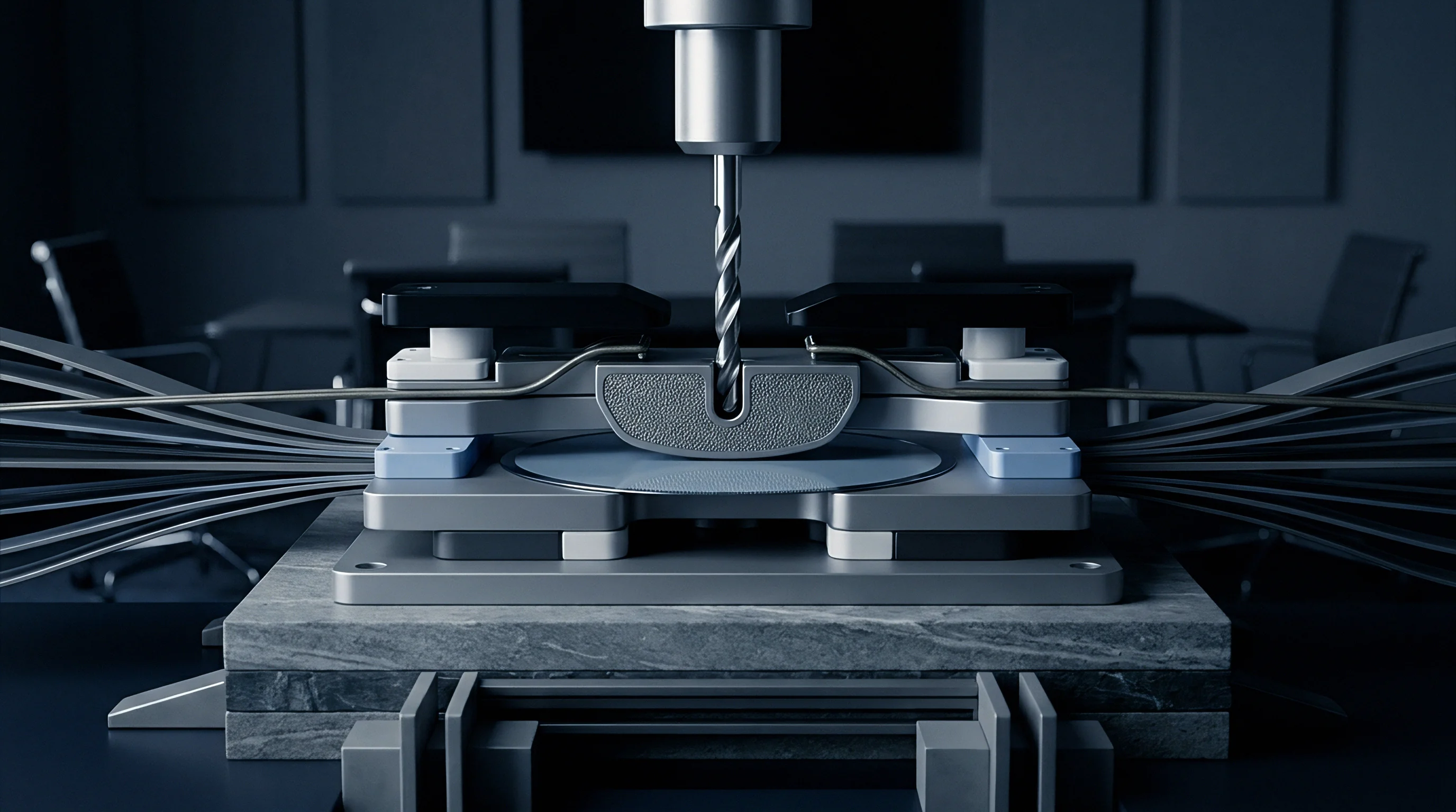
Sensors for In-Line Module Inspection
Contact probes with rubied stylus tips measure physical edge locations along three orthogonal axes. Non-contact laser displacement instruments capture vertical height maps across sensitive optical substrate surfaces without inducing mechanical stress. Sensor selection depends on material hardness and acceptable tactile deflection limits.
Confocal chromatic displacement sensors resolve surface topographies down to ten nanometers on highly reflective metallic interconnect pads. Triangulation lasers deliver higher data acquisition rates over ceramic substrates but suffer from optical scattering near unpolished substrate edges. Combining tactile touch-probes for primary datum location with laser sensors for surface profiling minimizes inspection cycle overhead while maintaining sub-micron measurement fidelity.
Baseline Surface Profiling in Automated Stations
Laser triangulation displacement instruments project microscopic line profiles across raw substrate surfaces to record topological height arrays. Calibration records prove physical system stability. High-speed digitizers convert analog sensor output into three-dimensional point clouds mapped to machine coordinate systems.
A physical workpiece shifts under dynamic mechanical clamping forces before secondary toolpaths execute.
Fixturing clamping pressure introduces localized mechanical deflection across thin-film substrates. Point-cloud processing algorithms filter out surface roughness artifacts while isolating macro-level substrate tilt and bow. Alignment software calculates plane-fit transformations to re-orient nominal tool paths relative to actual clamped substrate topographies.

Compensation
Modifying nominal Computer Aided Manufacturing toolpaths inside automated CNC stations demands real-time spatial matrix math. Static tooling paths compiled in off-line CAM software fail to account for dynamic tool wear, thermal expansion of linear motor stages, and part-to-part mechanical variations. Secondary toolpath adjustments execute dynamically by injecting calculated translational and rotational offset vectors into machine tool control buffers.
Micro-machining spindles expand along their axis as internal bearings heat during continuous operation. Spindle expansion reaching three micrometers destroys tolerance budgets on active photonic alignment grooves. Edge compute modules monitor embedded temperature sensors and recalculate Z-axis offsets every sixty seconds.

Coordinate Transformation Matrices for Secondary Adjustments
Multi-axis motion controllers map physical displacement vectors into six-degree-of-freedom translation matrices. The linear transformation updates nominal cutter location coordinates (X, Y, Z) and rotational orientation angles (A, B, C) in real time. Mathematical rotation matrices prevent rotational offset adjustments from introducing translational positioning errors at tool center point locations.
Dynamic tool offset calculations utilize homogeneous transformation matrices to chain workpiece offsets, tool length compensation, and spindle thermal growth vectors. Processing these matrix operations directly within the motion controller interpolation cycle prevents axis motion stutter and micro-segmenting errors along complex cutting paths, protecting micro-joint tolerances against thermal drift.

Worked Calculation of Multi-Axis Offset Vectors
Evaluating active optical mount alignment illustrates the mathematical execution of secondary toolpath adjustments. Consider an automated workstation machining alumina ceramic substrate mounts measuring 50 mm by 50 mm, with a material thermal expansion coefficient of 6.5 ppm per degree Celsius. Operating environment temperature rises by 4.2 degrees Celsius during continuous multi-shift production.
The active optical coupling tolerance budget sets a maximum allowable spatial deviation of 1.2 micrometers along the Z-axis.
Linear thermal expansion produces a dimensional shift calculated by multiplying initial length, expansion coefficient, and thermal differential: 50 mm multiplied by 6.5 times ten to the negative sixth power per degree Celsius multiplied by 4.2 degrees Celsius yields 0.001365 mm, or 1.365 micrometers. This physical growth exceeds the 1.2 micrometer tolerance budget by 0.165 micrometers.
The secondary CAM algorithm calculates a dynamic scaling offset matrix that scales nominal tool paths by 0.9999727 along X and Y axes while applying a negative 1.365 micrometer translation vector along the Z-axis. Applying this transformation matrix directly to nominal G-code motion routines lowers cutting tool Z-height across the substrate area, restoring physical mounting planes within specified tolerance thresholds.
| Parameter | Static CAD Toolpath | Secondary Dynamic Offset | Operational Impact |
|---|---|---|---|
| Positional Repeatability | +/- 8.5 micrometers | +/- 1.1 micrometers | Sub-micron placement accuracy |
| Substrate Scrap Rate | 4.2 percent | 0.3 percent | Direct yield improvement |
| Workstation Cycle Time | 14.2 seconds | 15.6 seconds | 1.4 second metrology overhead |
| Tool Wear Degradation | Uncorrected drift | Real-time offset update | Extended tool service life |
- 1. Datum Registration ~ Station vision probes capture primary substrate datum marks and calculate translation offsets relative to machine home coordinates.
- 2. Topological Surface Mapping ~ Non-contact optical displacement sensors sweep key reference planes to detect localized warping or tilt.
- 3. Matrix Transformation Calculation ~ Real-time edge compute nodes run spatial transformation algorithms to update nominal cutter coordinates.
- 4. Dynamic Toolpath Injection ~ Interpolated motion routines stream updated G-code displacement vectors directly into CNC axis buffer channels.
Iterative toolpath offset corrections settle within initial control cycles, preventing standing mechanical oscillation in high-speed linear gantry stages.


Telemetry
High-speed communication links between in-line sensors and motion controllers dictate the stability of closed-loop machining routines. Telemetry architecture must transmit spatial coordinate adjustments, sensor status signals, and controller acknowledgment packets without variable transmission delays. Signal transmission delays degrade cutting tool path fidelity during high-speed feed movements.
Industrial communication protocols utilize cyclic synchronous data transfers to guarantee sub-millisecond updates across machine automation nodes as edge compute modules process real-time sensor streams. Jitter in measurement packet arrival times creates artificial velocity step-changes in servo drives, resulting in visible chatter marks on finished module surfaces.

Closed-Loop Data Streams in Automated Workcells
Industrial Ethernet buses transmit coordinate adjustment arrays across fieldbus nodes at microsecond cycle times. Ethernet fieldbuses establish deterministic time slots for sensory feedback payload transmission. Sensor data buffering at fieldbus couplers prevents dropped packets during heavy control traffic bursts.
Fieldbus master controllers synchronize sensor sampling clocks with drive interpolation cycles. Hardware clock synchronization ensures spatial offsets apply to exact tool location points along the physical trajectory, eliminating manual operator intervention.

Where Does Secondary Offset Compensation Fail in Multi-Axis Tooling?
Systemic tracking errors surface when measurement sample rates lag behind high-speed cutting tool feed velocities. High feed rates combined with low sensor polling frequencies generate spatial gaps between measured points, causing interpolation algorithms to smooth over localized substrate surface defects and distort final substrate clearance.
A telemetry bus latency exceeding four milliseconds induces a spatial tracking divergence of two micrometers at cutting speeds above one hundred millimeters per second.
| Bus Architecture | Minimum Cycle Time | Packet Jitter | Spatial Shift at 100 mm/s | Determinism Rating |
|---|---|---|---|---|
| EtherCAT | 62.5 microseconds | < 1 microsecond | 0.006 micrometers | High |
| PROFINET IRT | 250 microseconds | < 1 microsecond | 0.025 micrometers | High |
| OPC UA TSN | 1.0 millisecond | 15 microseconds | 0.100 micrometers | Moderate |
| Modbus TCP | 50.0 milliseconds | 5.0 milliseconds | 5.000 micrometers | Unsuitable |
- Buffer Overrun Divergence ~ Excess spatial offset packets overload controller FIFO queues, causing axis freeze or micro-stoppages.
- Asynchronous Clock Drift ~ Unsynchronized master clocks between optical probes and motion axes produce out-of-phase displacement corrections.
- Quantization Noise Distortion ~ Low-resolution sensor bitstreams introduce micro-stepping ripples along finished workpiece edge profiles.
- Unfiltered Sensor Outliers ~ Dust particles or reflective flash generate false height spikes that trigger unnecessary local cutter retractions.
Whether edge-based neural network models can predict tool deflection patterns faster than deterministically calculated kinematic algorithms remains actively debated among control software architects.


Alignment
Transferring secondary CAM modification data across sequential automated assembly stations requires universal spatial coordinate definitions. Modular production lines pass micro-electronic workpieces through distinct dispensing, wire bonding, active alignment, and mechanical encapsulation cells. Substrate displacement offsets calculated at station one must pass cleanly to downstream workstations to prevent compounding spatial tracking errors.
Passing raw, vendor-proprietary spatial offsets creates compatibility barriers between machines built by different automation integrators. Standardized spatial exchange file formats allow downstream machine tools to interpret inherited surface modifications accurately.

Cross-Station Spatial Reference Systems
Automated production lines pass physical assemblies through multiple distinct machining, dispensing, and placement stations. Global fiducial marks etched onto carrier fixtures establish a shared coordinate baseline across all workstations. Calibration vision systems at each station locate fixture fiducials and compute local offset matrices relative to global fixture origins.
Inherited substrate warp data maps into localized station coordinates without requiring full secondary surface sweeps at every machine cell. Sharing spatial offset maps across cell boundaries reduces total line inspection overhead while preserving tight micro-assembly tolerances.

Standardization of Machine Interface Data Formats
Open data exchange specifications prevent software translation errors when sharing dynamic offsets between different CNC software platforms. Standard schemas define explicit XML and JSON structures for tool offsets, surface topography vectors, and fixture alignment transformations. Machine tool controllers parse standardized files directly into memory registers without manual file conversion steps.
Adherence to IPC-2581 XML schema extensions for dynamic offset data prevents geometric distortion when moving toolpath adjustments between automated machining stations.
| Data Format | Primary Scope | Schema Structure | Real-Time Latency | Interoperability |
|---|---|---|---|---|
| IPC-2581 | PCB Assembly and Tooling | XML Schema | Non-real-time batch | Universal |
| STEP-NC AP242 | Multi-Axis CNC Machining | STEP EXPRESS / XML | Low-latency stream | High |
| Umati OPC UA | Machine Tool Interface | OPC UA Information Model | Sub-millisecond stream | Broad |
| Proprietary Binary | Controller Native Motion | Vendor Specific Structure | Sub-microsecond | Closed Lock-In |
| Data structures evaluated based on multi-vendor automated cell integration tests under ISO 10303 guidelines. | ||||
- Coordinate System Standard ~ Define explicit origin datum nodes and positive axis directional vectors for every workstation.
- Offset Variable Scoping ~ Isolate dynamic transient offsets from persistent tool geometry wear registers inside controller memory.
- Schema Validation Rules ~ Implement strict XML or JSON schema checks to filter invalid numerical string formats prior to execution.
- Handshake Verification Protocols ~ Establish bidirectional hardware confirmation signals before releasing modified toolpaths to linear drives.
Incorporating ISO 14649-10 annex B into the tooling delivery contract obligates the machine integrator to expose standard STEP-NC feature modification vectors rather than compiled vendor binary offsets.


Custody
Defining intellectual property ownership for automated toolpath modification routines forms the commercial basis of module manufacturing contracts. Turnkey automation suppliers frequently bundle secondary CAM modification scripts into locked, proprietary controller firmware. Because landed costs reflect these unmodeled machining adjustments, brand owners purchasing automated module production lines require full access to post-processor source code, calibration algorithms, and offset calculation macro routines.
Lock-in occurs when secondary adjustment algorithms reside exclusively within supplier-owned software modules. Moving production to a secondary assembly facility becomes impossible without re-engineering toolpath modification logic from scratch. Sourcing scopes of work specify complete delivery of uncompiled source scripts, mathematical offset definitions, and software validation dossiers.

Division of Intellectual Property in Adaptive Manufacturing Scope
Automated tooling contracts frequently blur the boundary between proprietary supplier machine control software and buyer product design files. Machine builders retain rights to core motion control drivers, while module buyers hold exclusive ownership of product geometries and secondary adjustment macro scripts. Clear contractual boundary definitions prevent post-handover ownership disputes.
Detailed statements of work itemize all CAM post-processor files, custom macro routines, and vision calibration routines as explicit buyer deliverables. Securing non-exclusive licenses for core vendor motion firmware ensures long-term operational autonomy on the factory floor.
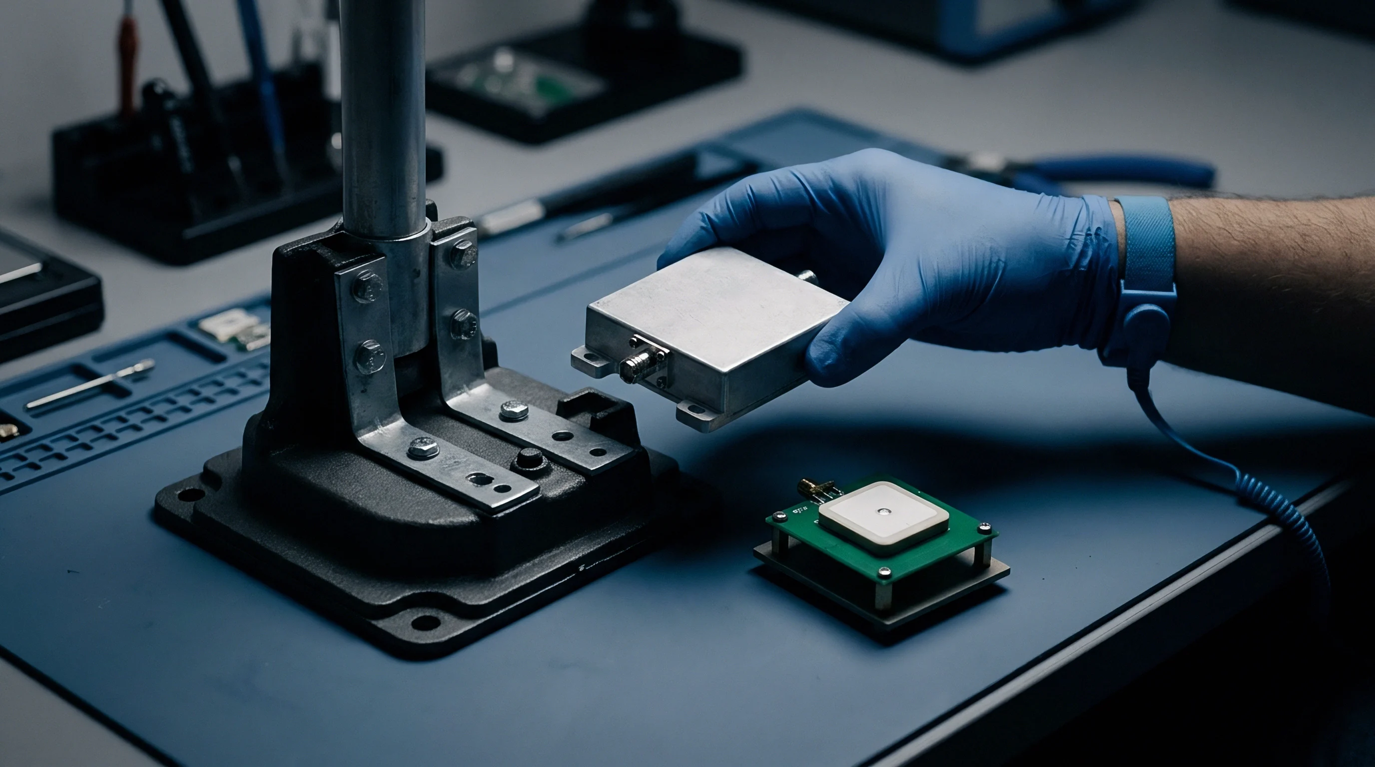
Commercial Mechanisms for Automated Tooling Deliverables
Non-recurring engineering quotations include explicit details for post-processor source code, macro routines, and calibration scripts. Break-even analysis accounts for software maintenance costs alongside hardware tooling expenditures. Unbundling engineering service fees from machine hardware unit prices illuminates true automation costs.
Retaining uncompiled CAM post-processor source files protects the module brand owner against single-source tooling lock-in during volume scaling.
Acceptance testing procedures demand verification of automated secondary CAM routines under extreme thermal and mechanical workpiece variations. Sign-off documentation includes audited source repositories, compiled binary verification hashes, and functional test logs. Failing to secure full source ownership of dynamic CAM modification routines forces module buyers to pay redundant non-recurring engineering fees whenever moving production to an alternate assembly partner.