High Temperature Polymer Melt Characterization in Tooling Channels
Characterizing high-temperature polymer melt rheology in tooling channels requires in-line pressure-temperature sensing to control shear degradation.
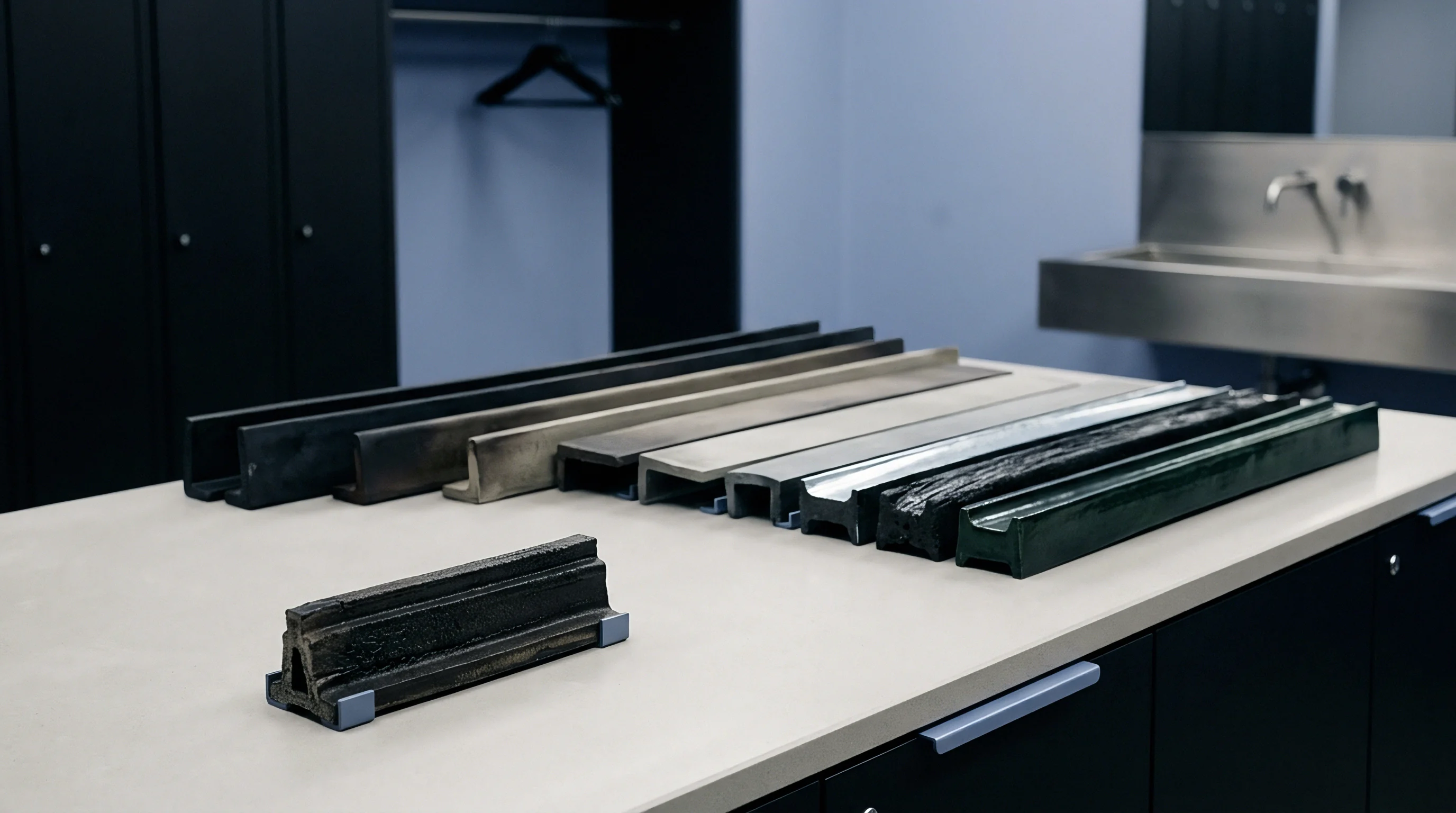

Bore
Capillary rheometer datasheets from resin suppliers record shear rates between 100 and 10,000 reciprocal seconds under static barrel conditions. In actual injection hot runners and cold feed gates, polyether ether ketone (PEEK), polyetherimide (PEI), and liquid crystal polymers (LCP) experience shear rates exceeding 50,000 reciprocal seconds at melt temperatures running between 360 and 410 degrees Celsius. Viscosity curves published in material qualification folders collapse under these conditions.
The resin suppliers measure flow using standard tungsten carbide dies with entry angles of 90 or 180 degrees, whereas feed channels feature complex geometric transitions, gate lands, and valve-pin interruptions. High shear fields generate severe viscous dissipation. The resulting heat elevates localized core temperatures well beyond the setpoint of the hot-runner heater band.
Melt viscosity in narrow passages dictates pressure drop, molecular orientation, and shear heating. Semi-crystalline resins like unfilled PEEK 450G display pronounced shear thinning alongside rapid crystallization kinetics when wall temperatures drop below 170 degrees Celsius. Amorphous resins like PEI Ultem 1000 present steady shear thinning with an exceptionally steep temperature-viscosity dependence.
A five-degree temperature shift inside the feed runner changes injection pressure by twelve to eighteen percent.
Unfilled polyether ether ketone at 380 degrees Celsius exhibits a forty-two percent drop in apparent viscosity when shear rate climbs from 5,000 to 45,000 reciprocal seconds inside a 1.2-millimeter gate land.
High-temperature polymers degrade when dwell times inside feed paths extend past acceptable residence windows. Thermal degradation of PEEK at 400 degrees Celsius produces chain scission, cross-linking, and outgassing of volatile compounds within two minutes of stagnation. These volatile compounds corrode tool steel, foul optical sensor lenses, and generate voids inside structural wall sections.
Engineering teams must evaluate effective residence volume against shot size. If the runner system holds three times the shot volume, polymer resides in the heated zone across four machine cycles. That exposure triggers catastrophic loss of mechanical ductility and dielectric isolation resistance.

Capillary Rheometry versus In-Cavity Shear Reality
Laboratory capillary barrels deliver steady-state Hagen-Poiseuille flow under clean isothermal assumptions. Tool channels operate in transient, non-isothermal regimes where polymer skins freeze instantly against tool steel kept at 180 to 220 degrees Celsius. The solidified skin narrows the effective hydraulic diameter of the flow path.
Shear stress concentrates in a thin annular boundary layer between the frozen layer and the molten core.
Wall slip becomes significant with fluoropolymers, liquid crystal polymers, and highly filled polyphenylenes. Glass-fiber-filled PPS exhibits slip velocities along the metal wall that invalidate no-slip boundary assumptions in commercial mold filling software. Melt fracture occurs when gate shear stress exceeds 0.3 megapascals.
The melt fractures geometrically, creating surface delamination, internal micro-voids, and weld-line weakness inside module housings.
| Polymer Grade | Processing Temperature Range | Critical Shear Stress Threshold | Maximum Safe Residence Time | Viscous Dissipation Sensitivity |
|---|---|---|---|---|
| PEEK Unfilled (450G) | 380 to 400 C | 0.28 MPa | 150 seconds | High |
| PEEK 30% Glass Filled | 385 to 410 C | 0.35 MPa | 120 seconds | Severe |
| PEI Unfilled (Ultem 1000) | 360 to 400 C | 0.22 MPa | 180 seconds | Moderate |
| PPS 40% Glass Filled | 315 to 345 C | 0.32 MPa | 90 seconds | Moderate |
| LCP 30% Glass Filled | 335 to 365 C | 0.40 MPa | 60 seconds | Low |
Runner systems designed solely from raw material vendor charts under-dimension runner cross sections. Small feed diameters minimize resin scrap, but they force injection presses to run at peak hydraulic pressure limits. Squeezing high-viscosity melts through undersized channels induces localized resin burning.
Runner sizing balances pressure drop against thermal degradation limits.

Sensor
Piezoelectric quartz transducers installed flush against runner walls capture dynamic pressure transients at microsecond resolution. In-line melt monitoring detects viscosity variation between virgin resin batches and regrind additions. Standard machine stroke transducers track screw position, but they miss pressure drop fluctuations inside the hot-runner manifold.
Cavity-mounted transducers capture only the final packing phase. Channel-mounted transducers expose melt rheology during the initial filling phase where flow dynamics determine part stability.
Infrared pyrometers mounted directly in the runner wall capture actual melt stream core temperatures rather than metal steel temperatures. High-temperature melts transmit infrared radiation across narrow spectral bands. Dual-wavelength optical pyrometers eliminate emissivity calibration errors caused by polymer thin films depositing on sapphire probe windows.
Combining pressure transducers with infrared pyrometers inside the primary feed channel creates an in-line rheometer. This instrumentation measures instantaneous apparent shear viscosity on every production stroke.
- Piezoelectric pressure transducers record dynamic pressure drops across fixed runner lengths to calculate apparent wall shear stress without disrupting flow patterns.
- Dual-wavelength infrared pyrometers quantify transient melt temperatures through sapphire windows to detect instantaneous shear heating anomalies.
- Combined pressure and temperature pins integrate miniature diaphragm sensors directly into gate inserts to track gate freeze timing.
- Heat flux transducers evaluate heat transfer coefficients across frozen boundary layers to reveal mold cooling imbalances.
Signal acquisition rates require careful configuration. A 100-hertz data acquisition rate misses pressure spikes occurring during gate entry. Hardware installations use 1,000-hertz sampling channels coupled with high-speed digital filters.
Raw voltage signals feed through charge amplifiers positioned within two meters of the tool to prevent signal degradation caused by plant electromagnetic interference.
Hot-runner pressure differentials reveal resin batch viscosity shifts ten cycles before optical part inspection cameras detect dimensional shrinkage defects.
Tool designers often place instrumentation pins in cold runner drop segments or overflow tabs. Melt characterization in these locations captures degraded, cold material. Valid rheological readings originate from the primary feed manifold upstream of split-line distribution blocks.
Sensors positioned in these zones survive temperatures exceeding 400 degrees Celsius and continuous cyclic pressures up to 250 megapascals.
Melt characterization instrumentation adds significant complexity to tool machining, wire routing, and mold maintenance. Omitting channel sensors blinds quality engineers to polymer degradation, leading to unexplained field cracking when degraded resin ships inside functional module housings.

Manifold
Hot-half distributions for high-temperature engineering resins require balanced runner lengths, polished flow channels, and externally heated manifolds. Internally heated torpedo systems introduce stagnation points where PEEK or PEI char and flake off into the part cavities. Externally heated distribution blocks allow gun-drilled channels with sweeping radius bends.
Polish specifications inside these channels call for mirror finishes down to Ra 0.2 microns. Rough channel surfaces create boundary layer stagnation, accelerating localized thermal degradation.
Thermal isolation between the heated manifold and the cold tool base demands precise mechanical calculations. The manifold runs at 390 degrees Celsius while the mold plates run at 190 degrees Celsius. Thermal expansion misaligns drop nozzles relative to gate apertures if the engineering team ignores thermal growth coefficients.
A 400-millimeter manifold expands by approximately 1.8 millimeters at operating temperatures. Nozzle tips bind, gall, or shear off against gate inserts when expansion clearances lack precision.
Cartridge heaters require independent zone control across the hot-half. Edge zones lose heat rapidly through radiation and conduction into tool support pillars. Center drops retain heat.
Single-zone control creates a forty-degree temperature gradient across multi-drop molds, destroying flow balance. Closed-loop PID controllers with secondary backup thermocouples maintain thermal uniformity within plus or minus one degree Celsius across all nozzle tips.
- Viscous dissipation raises melt temperature beyond degradation thresholds in restricted gate entries.
- Wall slip creates plug-flow velocity profiles that disrupt standard shear rate calculations.
- Gate freeze variation produces part-to-part weight disparities across multi-cavity layouts.
- Molecular orientation aligns polymer backbones along feed paths, inducing anisotropic shrinkage and warp.
Gate design choices govern the character of the melt entering the cavity. Submarine gates induce severe shear heating that chars sensitive engineering grades. Valve gates with hydraulic or pneumatic pin actuation provide clean mechanical shut-off, preventing gate vestige and stringing.
Valve pins disrupt flow symmetry within the nozzle tip. The annular flow around the pin creates a longitudinal weld line that persists into the molded part, reducing burst pressure resistance in pressurized fluidic module headers.
Machining tolerances on runner bores require boring and honing rather than conventional drilling. Tool shops frequently defend oversized gate wear by claiming high-temperature glass-filled resins inevitably erode tooling steel within normal preventive maintenance cycles.

Ledger
Module integration agreements assign financial responsibility for tooling design, rheological characterization, and scrap rates. Turnkey sourcing agreements bundle mold construction, runner instrumentation, and qualification runs into a single non-recurring engineering line item. Turnkey contracts leave tool ownership with the factory, denying the buyer access to raw CAD runner geometries and sensor logs.
Semi-custom integration frameworks separate tool design files, runner manifold engineering, and sensor packages into distinct line-item assets owned entirely by the buyer.
Rheological characterization expenses generate frequent commercial disputes between module buyers and contract manufacturers. Filling simulation software outputs depend entirely on the precision of the raw material database. Standard material files within commercial software packages often use thirty-year-old test points.
Running customized capillary rheometry with cross-die shear stress characterization costs between 8,000 and 15,000 dollars per resin lot. Sourcing agreements define which party pays for laboratory material characterization and who covers tool modifications if actual melt behavior diverges from simulation outputs.
| Integration Scope Level | Tooling Ownership Model | Rheology Characterization Scope | Non-Recurring Engineering Range | Design Transfer Portability |
|---|---|---|---|---|
| Turnkey Contract | Factory retains mold base | Vendor standard database | $40,000 to $70,000 | Zero portability |
| Semi-Custom Tooling | Buyer owns hot-half and inserts | In-line sensor data validation | $85,000 to $130,000 | High portability with files |
| Reference Design Build | Buyer licenses cavity geometry | Supplier unverified datasheets | $25,000 to $45,000 | Low portability |
| Full Custom Engineering | Buyer owns all files and tooling | Empirical high-shear lab testing | $140,000 to $220,000 | Full legal and physical ownership |
Mold base maintenance and sensor replacement costs accumulate quickly on high-temperature programs. Sapphire pyrometer lenses require replacement every 50,000 cycles due to abrasive glass-fiber scoring. Pressure transducer diaphragms drift after exposure to continuous thermal cycling.
Maintenance contracts mandate preventative sensor recalibration schedules and delineate scrap liability when drifting sensors fail to catch under-filled parts.
Section 8.4 of the Tooling Transfer Agreement dictates that complete raw in-line sensor logs and hot-runner manufacturing drawings transfer to the buyer upon completion of the preliminary qualification run.
Tooling qualification follows a structured sequence through specific verification gates:
- The mold maker submits detailed runner manifold thermal expansion calculations alongside raw sensor channel placement drawings for engineering review.
- The qualification lab performs empirical capillary rheometry across three temperature points to generate viscosity curves matching current resin lot numbers.
- The technician dry-cycles the mold to verify heater band resistance, thermocouple polarity, and sensor communication protocols at 400 degrees Celsius.
- The engineering team runs short-shot filling studies to establish physical shear thinning transitions against calculated pressure drops.
- The quality inspector measures physical part shrinkage, warp, and internal void presence across twenty consecutive continuous production cycles.
When procurement teams execute agreements under standard commercial purchase orders without technical attachments, standard factory terms prevail. The factory builds tools according to internal shop practices, and the buyer assumes full financial liability for dimensional scrap caused by uncharacterized melt viscosity swings.

Transfer
Relocating high-temperature tooling across manufacturing sites reveals hidden dependencies in auxiliary equipment. A tool qualified on an injection press equipped with high-response servo-electric valves behaves differently when transferred to an older hydraulic press. Screw recovery rates, back pressure control, and injection acceleration profiles alter the shear history experienced by the polymer melt inside the feed system.
Transfer protocols require documentation of machine hydraulic response rates, screw compression ratios, and barrel heater zone layouts alongside basic tonnage ratings.
Auxiliary mold temperature control units present another point of failure during site transfers. PEEK tooling demands oil-based or pressurized-water temperature controllers capable of maintaining 200 degrees Celsius across the mold core and cavity plates. Insufficient heating capacity or inadequate pump flow rates cause localized cooling line temperature drops.
The frozen layer inside the runner thickens, narrowing the effective flow bore and spiking injection pressures beyond machine safety limits.
Tool transfers between contract manufacturing plants require matched screw compression ratios and identical manifold controller firmware to maintain stable melt shear viscosity windows.
Resin pre-drying parameters require rigorous enforcement across transfer operations. Polyetherimide absorbs atmospheric moisture rapidly. Humid resin processed at 380 degrees Celsius undergoes severe hydrolytic degradation within the tooling channels.
Melt viscosity drops instantly, causing flashing, splay, and mechanical embrittlement. Desiccant dryers at the receiving facility must achieve dew points below minus 40 degrees Celsius, maintaining drying hoppers at 150 degrees Celsius for at least four hours before molding begins.
Second-source validation relies on physical parts matching baseline master records. Quality teams compare part weights, gate vestige dimensions, and optical ash content across both manufacturing sites. In-line sensor pressure signatures provide the definitive comparison.
When the pressure-time curve inside the primary runner matches the baseline signature from the original qualification trial, the melt experiences identical shear and thermal histories.
Engineering teams must decide how many production cycles a second-source vendor runs before the transfer dossier receives formal sign-off, leaving open the question of whether short-term stability proves long-term tool fatigue resistance under continuous 400-degree thermal cycles.