Post Transit Axis Realignment Protocols for Five Axis CNC Machine Tools
Complete physical leveling, guide rail realignment, and kinematic center calibration before committing numerical volumetric compensation tables to machine memory.


Slab
Transit shock indicators on the column show whether the crate took impacts over three times gravity during shipping, while three-axis accelerometers log any severe low-frequency resonance caused by transport trucks, ocean freighters, or rail cars. Once on site, riggers uncrate the five-axis machining center, check structural castings for micro-fractures, and inspect linear guide raceways for brinelling.
Factory transit brackets keep the axes locked in place, but hauling heavy cast-iron or mineral-cast frames over long distances still introduces structural twist. Service crews release these fixtures only after the base sits on its permanent pad. Placing a high-precision five-axis machine directly onto an unverified shop floor ruins geometric stability; the builder structural drawings specify a dedicated soil-isolated concrete pad between 400 and 800 millimeters thick, complete with isolated expansion joints and high-tensile anchor pockets.

Transit Shock Triage and Frame Settling
Riggers loosen the shipping brackets and tie-down turnbuckles so trapped mechanical stresses can work themselves out of the frame. Clamps on the rotary-tilt trunnion table lock the B-axis and C-axis during transit, shielding the direct-drive torque motors and internal duplex roller bearings from dynamic shock. Technicians run through a baseline diagnostic sequence before tying into shop power.
- Inspect external tri-axial shock indicators on machine columns and electrical cabinets to verify transport acceleration remained below the factory trip threshold of 3.0 g.
- Unbolt shipping brackets from the X, Y, and Z linear slideways, followed by the B-axis tilt housing and C-axis rotary platter locking fixtures.
- Remove protective cosmoline and barrier coatings from ground reference surfaces, linear guide rails, and precision ball screws using approved non-corrosive solvent washes.
- Install precision leveling wedges beneath every foundation jacking bolt point, spacing them per the manufacturer machine installation blueprint.
- Torque foundation anchor studs into structural chemical grout capsules, allowing a full seventy-two-hour chemical cure before applying clamping preload.
- Energize control systems and auxiliary hydraulic pumps to lubricate guideway trucks before commanding linear axis motion.
When foundation grouting cures, shrinkage pulls down unevenly on anchor studs and cocks the machine bed out of level. Technicians track the grout temperature with contact probes to ensure exothermic stabilization has finished before applying final torque.
Level the foundation anchor pack before checking guide rail squareness, because mechanical bed twist introduces false angular errors across all orthogonal planes.

Foundation Anchoring and Initial Leveling
Technicians clear the concrete pad surface and set precision three-point leveling wedges under the main jacking points. Kinematic three-point mounting avoids locking indeterminate stress loops into the bed casting during initial height adjustments. Dual-axis electronic levels, reading down to 0.001 millimeters per meter, sit directly on the scraped cast-iron reference surfaces along the base.
The bed leveling tolerance of 0.010 mm per meter relies on standard electronic levels calibrated at 20 degrees Celsius, a baseline that drifts whenever the shop floor temperature swings more than 1.5 degrees Celsius over 24 hours. Turning the foundation bolts brings the main guideways into an initial horizontal plane. Once the three primary wedges establish that plane, crews run secondary support jacks into light contact with the base pads while watching the electronic levels to ensure nothing twists.
Anchor pullout torque under dynamic cutting loads often degrades by roughly 12 percent across the initial 500 operating hours. Because empirical data on cyclic anchor fatigue varies across aggregate mixes, buyers mandate an anchor retorque protocol thirty days post-commissioning. Loading green grout too early causes micro-fractures along anchor sleeves, producing permanent axis tilt that leaves no remedy short of re-machining the base pads.

Datum
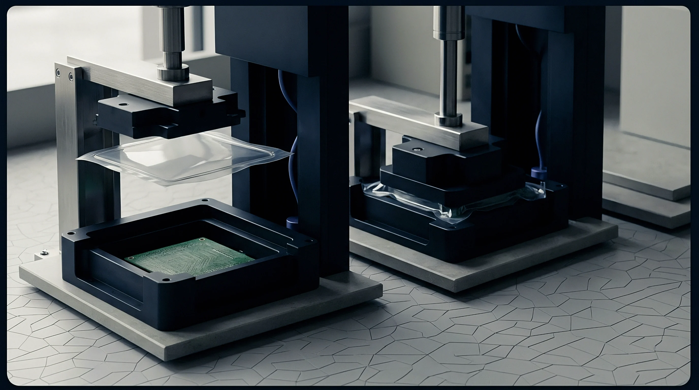
Granite master squares and dual-axis electronic levels establish the spatial baseline across the X, Y, and Z axes. Transit vibration displaces linear guide trucks, loosens reference edge gibs, and shifts ball screw end-support bearing housings. Re-establishing the mechanical datum requires measuring straightness, pitch, yaw, and roll on every linear axis before running software compensation routines.
Linear axes form the kinematic foundation for rotary-tilt tables or articulating milling heads. An uncorrected out-of-square condition between the X and Y axes creates elliptical errors during circular interpolation, compounding into severe volumetric distortion once the rotary axes tilt under full tool center point management.

Orthogonal Guide Rail Geometry Inspection
Autocollimators measure pitch, yaw, and roll along the linear slideways through their full travel. Technicians mount optical target mirrors on the spindle carrier or table saddle, indexing the axis in 50-millimeter steps while recording angular tilt against a collimator head mounted on an isolated tripod.
| Error Parameter | Measurement Instrumentation | ISO 230-1 Allowance | Post-Transit Typical Shift | Mechanical Correction Method |
|---|---|---|---|---|
| Straightness in Horizontal Plane (EXY, EYX, EZX) | Granite Straightedge and LVDT Probe | 0.005 mm / 1000 mm | 0.008 to 0.015 mm | Jack screw adjustment against master rail reference edge |
| Straightness in Vertical Plane (EXZ, EYZ, EZZ) | Dual-Axis Electronic Spirit Level | 0.004 mm / 1000 mm | 0.006 to 0.012 mm | Wedge pack shimming under bed support points |
| Angular Roll Error (ERX, ERY, ERZ) | Differential Electronic Level Pair | 0.006 mm / m | 0.010 to 0.020 mm / m | Foundation leveling bolt torque redistribution |
| Angular Pitch Error (EKX, EKY, EKZ) | Laser Autocollimator System | 0.008 mm / m | 0.012 to 0.025 mm / m | Linear guide rail clamping torque retensioning |
| Angular Yaw Error (EMA, EMB, EMC) | Laser Autocollimator System | 0.008 mm / m | 0.010 to 0.022 mm / m | Reference shoulder realignment via precision indicators |
| Axis Squareness (CXY, CXZ, CYZ) | Granite Master Square and Indicator | 0.006 mm / 500 mm | 0.015 to 0.035 mm | Gantry dual-drive electronic skew offset recalibration |
Mechanical alignments take priority over numerical software compensation. Attempting to mask guide rail waviness or bed twist by overloading controller pitch error tables creates dynamic instability down the line: linear trucks ride against distorted raceways, causing accelerated bearing wear and friction spikes that show up directly on machined surfaces at high feed rates.

Squareness Measurement across Orthogonal Planes
Dial test indicators mounted to the spindle nose sweep granite reference squares to catch perpendicularity errors. Checking squareness between horizontal axes calls for a Grade 00 granite square laid flat on the table, dialed parallel to the primary reference axis before the indicator sweeps the perpendicular face along the cross axis stroke.
- Gantry Skew Desynchronization develops when transport shocks cause independent dual-drive servomotors on gantry bridges to slip relative to absolute scale zero marks, skewing the crossbeam out of perpendicularity.
- Linear Rail Wedge Shifting occurs when guide rail mounting bolts lose factory clamp torque during road transit, letting the precision rail shift laterally against the cast locating shoulder.
- Ball Screw Axial Runout results from transit shock displacing double-nut angular contact thrust bearings, generating cyclic drunken-thread errors during axis traverse.
- Guideway Gib Looseness surfaces when tapered adjustment gibs slide backward in transit, producing excessive lateral carriage float during directional reversals.
Correcting gantry squareness requires rebalancing synchronization across master and slave servo drives. Technicians adjust controller parameter offsets for the slave axis grid position until the crossbeam sweeps square to the guideways.
Under ISO 230-1 Section 4, failure to record environmental temperature soak histories before linear axis calibration releases the builder from positioning repeatability guarantees.
Adherence to ISO 230-1 Clause 4.2 obligates the field technician to document thermal steady-state conditions before recording squareness data, which prevents the builder from disclaiming warranty liability for geometry-induced tool wear.


Kinematics
Rotary axis alignment defines the spatial relationship between the spindle taper and the trunnion center of rotation. Five-axis architectures depend on precise spatial intersections between linear travel vectors and rotational centerlines. Trunnion tables with tilting B-axes and rotary C-axes or articulating spindle heads with swivel A-axes and B-axes suffer mechanical shifts during transit rigging.
CNC controllers run kinematic transformations through vector calculations that assume nominal distances between rotary axis pivot lines and the spindle gauge line. An uncorrected shift of twenty micrometers in the B-axis pivot center leads directly to gouging whenever the tool tilts during simultaneous five-axis surface milling.
Rotary Centerline Location and Eccentricity
Precision test arbors mounted in the spindle sweep high-resolution displacement probes around the swivel housing. Technicians position a calibrated reference sphere on the machine table, commanding the linear axes to track the sphere while rotating the B-axis or C-axis through its angular envelope. The distance between the physical center of rotation and the programmed kinematic zero point must be verified to sub-micron accuracy.
| Kinematic Parameter | Error Mechanism | Diagnostic Tool | Calibration Target | CNC Parameter Target |
|---|---|---|---|---|
| B-Axis Center of Rotation (X Offset) | Trunnion housing lateral transit shift | R-Test Sensor Cluster | Within 0.003 mm of nominal | Center of Rotation X Register |
| B-Axis Center of Rotation (Z Offset) | Support bracket vertical settlement | R-Test Sensor Cluster | Within 0.003 mm of nominal | Center of Rotation Z Register |
| C-Axis Platter Radial Runout | Table bearing transit shock brinelling | High-Precision Test Arbor | Within 0.002 mm over 360 deg | Spindle Dynamic Runout Map |
| B-to-C Axis Orthogonality | Trunnion frame angular twist | Granite Square and Dial Gage | Within 0.005 mm / 300 mm | Kinematic Transform Tilt Angle |
| C-Axis Center of Rotation (Y Offset) | Table mounting register lateral shift | Calibrated Datum Sphere | Within 0.003 mm of nominal | Center of Rotation Y Register |
The rotary centerline intersection tolerance of 0.005 mm rests on manufacturer baseline R-test records under static thermal equilibrium. This parameter moves if hydraulic counterbalance pressures fluctuate or if structural thermal expansion shifts the head casting during high-speed spindle operations. Technicians apply mechanical dial gages to verify that the face runout of the rotary table platter remains true throughout complete revolutions before executing electronic probe cycles.
Should Centerline Offsets Precede Table Dynamic Tuning?
Static geometric errors must be isolated before tuning servo feed-forward parameters; otherwise, loop gains simply mask mechanical misalignments rather than correcting dynamic lag. Tuning drives on an axis whose physical pivot point sits ten micrometers away from programmed space forces the loop to demand uneven accelerations. Dial test indicators trace the reference sphere across positive and negative quadrant boundaries to verify true position.
- Thermal Stabilization Soak demands that the machine spindle and rotary axis direct-drive torque motors cycle at operational speeds for four hours to achieve thermodynamic equilibrium before capturing kinematic probe positions.
- Probe Calibration Against Master Artifact requires calibrating the touch-trigger or scanning probe against an optical reference ring gage to eliminate internal styli deflection and ball lobing errors.
- Trunnion Bearing Preload Verification involves measuring rotational breakaway torque on the B-axis cradle using a calibrated torque wrench to confirm transit shocks did not pinch bearing cages.
- Multi-Angular Sphere Measurement executes an automatic macro that rotates the B and C axes through thirty-six distinct compound orientations, recording linear axis tracking errors via three-dimensional touch probing.
Modern CNC systems feature automated calibration cycles, such as kinematic analysis software cycles, which probe a precision master sphere mounted to the table in multiple positions. The controller calculates the spatial offset values and updates the machine internal kinematic matrix registers automatically. Align physical rotary axis centerlines to mechanical zero before generating electronic software offset tables.
Volumetrics
Laser trackers using multi-lateration techniques measure spatial positioning errors across the complete three-dimensional work envelope. Moving beyond classical static axis-by-axis checks, modern high-accuracy five-axis machine tools require full volumetric spatial verification post-transit. Structural distortions, combined axis squareness errors, and linear positioning deviations synthesize into complex spatial displacement vectors that vary depending on tool position within the machining volume.
Conventional laser interferometers check one linear axis at a time, capturing positioning accuracy, straightness, pitch, and yaw along single paths. Volumetric compensation models compile all twenty-one kinematic error components of a three-axis Cartesian structure, comprising three positioning errors, six straightness errors, nine angular errors, and three squareness errors, generating a unified three-dimensional correction vector field.

Multi-Line Laser Tracker Spatial Mapping
Spindle-mounted retroreflectors track diagonal trajectories in accordance with ISO 230-6. Either multiple tracking units or a single unit running sequential multilateration establish absolute coordinates across hundreds of distributed points throughout the working volume.
A thermal variation exceeding 1.2 degrees Celsius across the machine bed during laser interferometry invalidates pitch compensation arrays for travels beyond 1000 millimeters.
Civil engineering standards for deep-bore seismic isolation pylons in semiconductor cleanrooms face the same long-period ground waves that perturb machine shop floors adjacent to heavy rail spurs. Soil harmonic resonance propagates through standard slab isolators unless decoupling joints isolate the foundation perimeter. Precision machine tool foundations require comparable isolation trenches to prevent external heavy machinery vibrations from corrupting spatial multi-lateration measurements.
| Working Volume Size | Tracked Grid Points | Calibration Time | Uncompensated Spatial Error | Compensated Spatial Error |
|---|---|---|---|---|
| Small (500 x 500 x 400 mm) | 216 points (6x6x6 grid) | 4.5 hours | 0.022 mm maximum | 0.004 mm maximum |
| Medium (1000 x 800 x 700 mm) | 512 points (8x8x8 grid) | 8.0 hours | 0.038 mm maximum | 0.007 mm maximum |
| Large (2000 x 1500 x 1000 mm) | 1000 points (10x10x10 grid) | 14.5 hours | 0.065 mm maximum | 0.012 mm maximum |
| Extended Bridge (4000 x 2500 x 1500 mm) | 1728 points (12x12x12 grid) | 22.0 hours | 0.110 mm maximum | 0.018 mm maximum |
Environmental sensors logging ambient temperature, machine tool structural casting temperatures, air pressure, and relative humidity run continuously during the spatial grid measurement. The software calculates thermal expansion coefficients and normalizes measurement data back to the international reference standard temperature of 20 degrees Celsius. Applying raw volumetric compensation tables gathered in a varying thermal shop floor environment introduces artificial spatial waviness into machine tool axes.

Will Foundation Creep Invalidate Volumetric Maps?
Subsurface soil shifts warp machine beds over months, rendering static numerical compensation matrices unreliable over long production runs. As foundation concrete continues to cure and settle under dynamic floor loads, the machine frame flexes at its anchor points. Volumetric maps generated within seventy-two hours of uncrating will drift as the underlying mechanics move under operational forces.
Technicians verify compensation maps using circular interpolation checks across multiple planes. The double ballbar test, conducted in accordance with ISO 230-4, serves as a high-speed verification method to validate contouring behavior across interpolated planar arcs. Comparing dynamic ballbar traces captured before and after software compensation confirmation highlights whether residual mechanical backlash or servo mismatch remains hidden within the spatial volume.
The industry leaves unresolved whether software-based volumetric compensation masks ongoing physical foundation settlement until the linear guide recirculating packs experience premature spalling.


Acceptance
Final commissioning protocols converge on physical cutting trials that validate the entire mechanical, kinematic, and numerical error correction chain. Synthetic electronic measurements confirm static alignment, yet dynamic machining conditions, cutting forces, tool deflection, and spindle thermal growth expose the real capabilities of the realigned five-axis machine tool.
Machine purchase agreements delineate factory acceptance testing at the builder site from site acceptance testing at the customer facility. The transfer of warranty liability and the release of final milestone retainage payments rest on executing the site acceptance protocol without dimensional deviations exceeding part blueprint tolerances.
Standard NAS Test Piece Machining
Machinists clamp an aerospace-grade aluminum alloy billet onto the rotary platter. The National Aerospace Standard NAS 979 circle-diamond-square test part provides the benchmark for dynamic five-axis contouring precision, combining a circular boss, an angled square, and a diamond contour machined under continuous multi-axis tool orientation changes.
CMM inspection of the finished NAS 979 test specimen reveals dynamic tracking errors that static indicators miss. The circular profile verifies contouring accuracy and squareness under high feed rates. The diamond angles expose servo reversal spikes, axis backlash, and quadrant transition steps.
The angled square highlights the accuracy of the rotary axis centers of rotation, as any error in the kinematic software registers translates into stepped facet mismatches across corner blend intersections.
Dynamic trunnion deflection under cutting torque exposes structural weaknesses that static dial indicator inspections cannot register.
Money moves on these answers when a single missed trunnion eccentricity scraps fifty thousand dollars of titanium blisk forgings on the first production run. Plant managers maintain strict adherence to documented site sign-off tolerances. If the finished test piece displays gouging, chatters, or out-of-roundness exceeding ten micrometers, the acceptance remains blocked, preventing builder field technicians from declaring commissioning complete.

Site Sign-Off and Warranty Activation
Plant managers review coordinate measuring machine inspection reports against the factory purchase order tolerances before endorsing final delivery documents. Handover scopes require exact alignment between the factory acceptance test run sheets and the customer site acceptance documentation. If transport vibration altered mechanical squareness, the builder must re-shim and physically realign the machine guide rails rather than solely applying software offset compensations.
Dynamic cornering gouges on the NAS 979 test piece often stem from uncompensated rotary table servo lag rather than coolant temperature variations.