Meaning
Standardized micro-gauge electrical wire specifies a nominal solid metal diameter of approximately two mils or 0.050 millimeters for ultra-compact signal routing. Within miniature electronics, an awg 44 conductor provides the physical channel for low-current transmission through tight mechanical hinges, wearable sensor harnesses and micro-coaxial transmission lines. The classification establishes cross-sectional copper area, standard resistivity values and baseline pull-strength thresholds for production verification.
Physical utility terminates where current density demands induce thermal failure or where continuous mechanical vibration exceeds the work-hardening endurance limit of bare drawing stock.
Current Capacity
Thermal dissipation within high-density wire bundles sets strict boundaries on allowable operating current. An awg 44 conductor exhibits nominal electrical resistance near 8.5 ohms per meter at twenty degrees Celsius, converting excessive signal or supply currents into localized heating. Continuous loads exceeding seventy milliamperes raise core wire temperatures beyond standard fluoropolymer jacket ratings.
Because thermal dissipation drops inside encapsulated multi-conductor bundles, system integrators derate maximum sustained current to prevent dielectric degradation.
Termination Stress
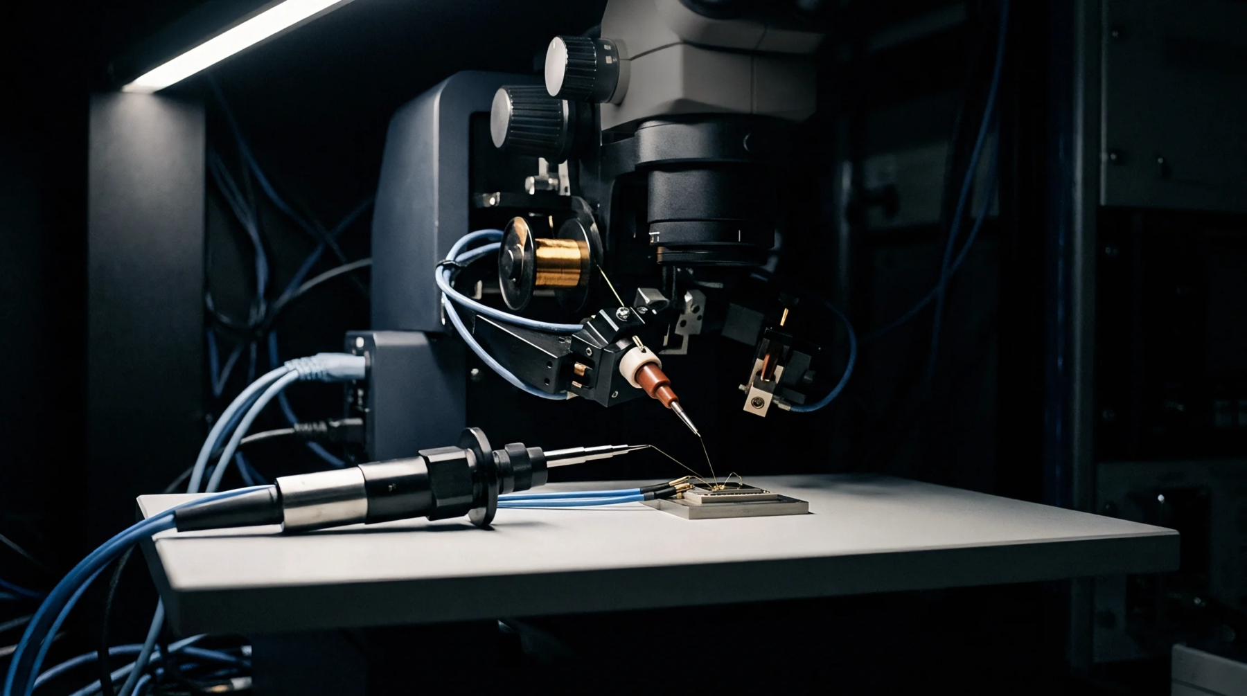
Mechanical termination of fine gauge wire relies on specialized thermal compression or laser ablation methods. Ultrasonic welding bonds each awg 44 conductor directly to gold-plated printed circuit board pads without crushing the ultra-thin copper core. Soldering remains prone to copper dissolution, where liquid solder leaches the narrow conductor cross-section within seconds of contact.
Clamping crimps are mechanically unviable due to the absence of bulk copper mass needed to support terminal barrel deformation. Solder joint inspection requires cross-sectional metallurgical polishing to confirm intermetallic layer thickness.
Dynamic Flexure
Micro-gauge wire routing through moving joints requires careful control of bend radii and jacket tension. Repeated flexing creates crystalline dislocations across the drawn metal grain, promoting fatigue cracks at hinge transitions. Enclosure designers preserve a minimum bend radius equal to ten times outer cable diameter to avoid localized strain accumulation.
Production qualification subjects test harnesses to cyclic folding protocols while recording micro-ohm resistance shifts to detect broken strands before functional failure occurs. Fatigue life drops precipitously when insulation materials grip the metallic core unevenly across thermal extremes. Testing under cyclic mechanical displacement validates long-term interconnect reliability inside mobile device enclosures.