Micro Coaxial Cable RF Insertion Loss Breakdown Mechanisms
Micro coaxial insertion loss stems from skin-depth conductor resistance, polymer dielectric dissipation, braid leakage, and crimp-induced reflections.


Skin
A 150-millimeter run of 0.81-millimeter micro coaxial cable drops 0.95 dB of signal power at 5.8 GHz before reaching the ceramic patch antenna. That single physical jumper consumes forty percent of the entire link margin allocated to an indoor Wi-Fi transceiver operating under standard regulatory EIRP ceilings. Conductor attenuation dominates this loss envelope across sub-gigahertz, 2.4 GHz, and mid-band cellular allocations.
High-frequency alternating currents crowd into an increasingly thin outer layer of the central conductor and the inner perimeter of the shield braid. At 2.4 GHz, the electromagnetic skin depth in standard annealed copper shrinks to 1.33 micrometers. By 6 GHz, current circulates within a metallic depth of merely 0.84 micrometers.
RF resistance scales inversely with the active conductor cross-section and proportional to the square root of carrier frequency. Center conductors in micro coaxial lines typically feature seven-strand silver-plated copper-clad steel or solid silver-plated copper wires measuring between 36 AWG and 44 AWG. Silver plating provides an initial conductivity improvement because pure silver exhibits five percent higher bulk conductivity than copper.
However, the surface profile of micro-wire drawing introduces microscopic valleys and ridges. When root-mean-square surface roughness matches or exceeds the skin depth, current paths trace the physical contours of the asperities. This geometric path lengthening drives effective high-frequency resistance twenty to forty percent above classical smooth-surface calculations.
A 0.81-millimeter jumper measuring 100 millimeters yields 0.62 dB total insertion loss at 5.8 GHz when tested under a fifty-ohm source and load impedance.
The operational penalty lands directly on receiver sensitivity. Link budgets for long-range 868 MHz LoRa channels tolerate fractional transmission line loss because sub-gigahertz skin depth remains above 2.1 micrometers, limiting 100-millimeter line attenuation to roughly 0.18 dB. Conversely, Wi-Fi 6E links pushing 160 MHz channel bandwidths at 6.5 GHz suffer aggressive signal degradation across the same physical run.
Thermal noise generated inside lossy jumpers degrades front-end noise figures milliwatt for milliwatt. Transmit chains push power amplifier stages toward saturation to overcome these line drops. Elevated thermal dissipation drains secondary battery cells and forces system throttling during sustained packet transmission bursts.


Dielectric
Insulation materials surrounding the center wire dissipate electromagnetic field energy through alternating electric polarization cycles. While conductor loss grows with the square root of frequency, dielectric dissipation increases linearly with frequency. Fluorinated ethylene propylene and polytetrafluoroethylene form the bulk of micro-coaxial dielectric constructions.
The loss tangent, representing the ratio of lost energy to stored energy per oscillation cycle, determines absolute dielectric dissipation. Solid fluoropolymers exhibit a dissipation factor near 0.0002 to 0.0007 across commercial communication bands up to 6 GHz. Foamed fluoropolymers introduce microscopic gas cells that depress the effective dielectric constant from 2.1 toward 1.4, simultaneously reducing capacitive charging currents and volumetric dissipation.

Where Does Dielectric Polarization Overtake Conductor Loss?
Cross-over points depend entirely on outer cable dimensions. Small physical diameters force electromagnetic fields into tighter spatial volumes, multiplying current densities along the center core. In 0.81-millimeter constructions, conductor attenuation remains the primary contributor beyond 10 GHz because the microscopic 44 AWG center strand exhibits extreme surface-to-volume resistance.
In heavier 1.37-millimeter and 1.78-millimeter lines, outer conductor radius increases and resistance drops significantly. Dielectric attenuation claims an expanding proportion of the total attenuation ledger above 5 GHz as polarization cycles outpace resistive drag.
| Cable Outer Diameter | Center Conductor Gauge | Conductor Loss at 2.4 GHz (dB/m) | Dielectric Loss at 2.4 GHz (dB/m) | Total Attenuation at 6.0 GHz (dB/m) |
|---|---|---|---|---|
| 0.81 mm | 44 AWG | 2.80 | 0.35 | 5.20 |
| 1.13 mm | 32 AWG | 1.60 | 0.30 | 3.10 |
| 1.32 mm | 30 AWG | 1.35 | 0.28 | 2.65 |
| 1.37 mm | 30 AWG | 1.15 | 0.25 | 2.35 |
Thermal acceleration shifts dielectric parameters during operation. Polymeric molecular chains exhibit higher rotational compliance as ambient operating temperatures move from 20 degrees Celsius toward industrial limits of 85 degrees Celsius. The dissipation factor climbs predictably, causing cable loss to increase by approximately 0.2 percent per degree Celsius.
Designers operating battery-powered asset trackers in desert enclosures face unpredicted link fades when cumulative jumper losses widen by half a decibel under midday solar loading.
The exact interaction between microscopic void distribution in foamed polymers and localized impedance shifts under variable field humidity remains subject to ongoing laboratory dispute.
Braid
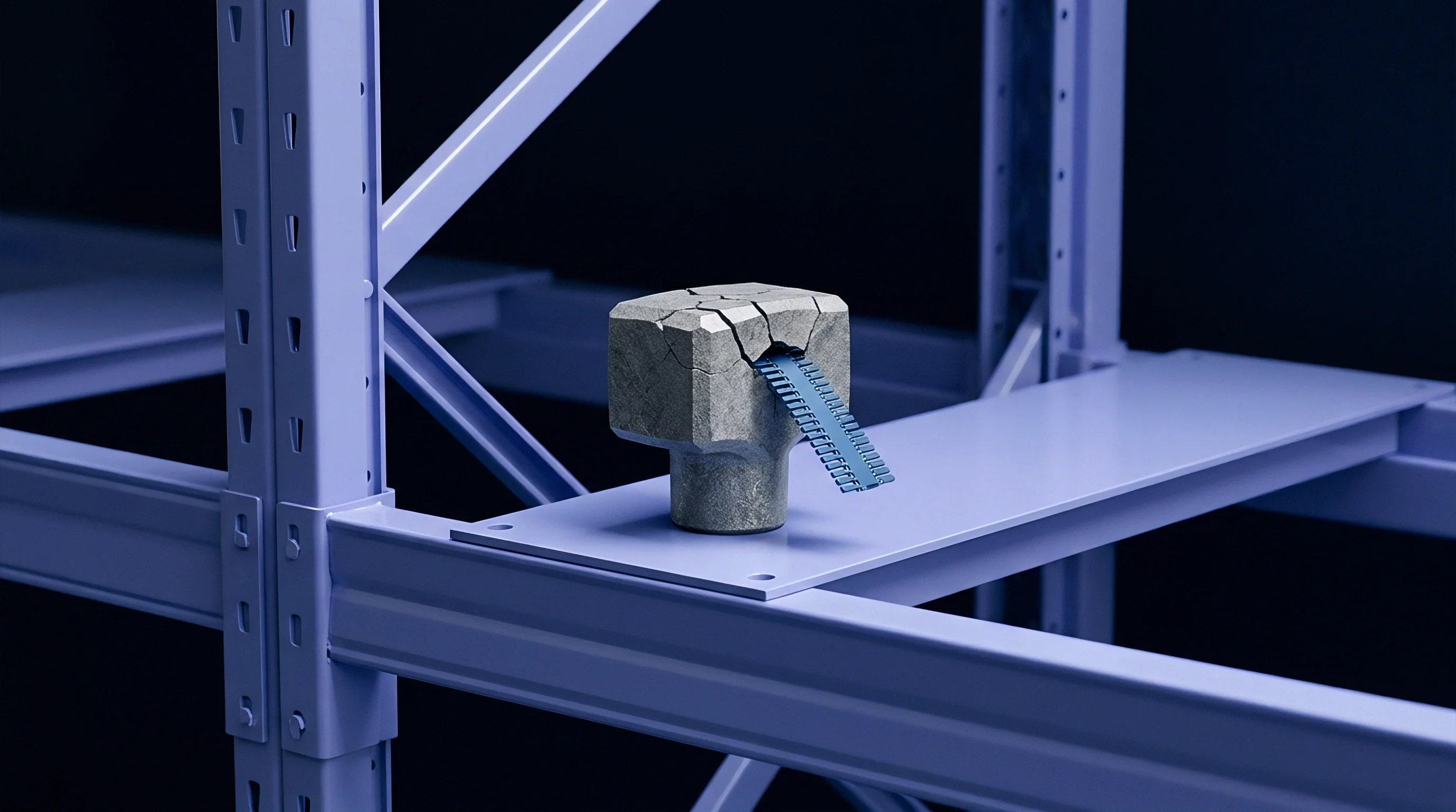
Micro coaxial outer conductors consist of woven or spiral-served silver-plated copper strands rather than solid tubular shields. Solid metal tubes deliver zero high-frequency leakage, but they crack instantly under tight bend radii within mobile housings. Shield braids introduce two distinct loss mechanisms: internal contact resistance between crossing strands and RF leakage into the chassis cavity.
Current traversing the braid must weave through interwoven wire bands. Microscopic surface oxidation and irregular contact pressures between adjacent wires force current through tortuous geometric paths. This phenomenon, known as current constriction, elevates the shield component of high-frequency resistance far above theoretical seamless copper cylinders.
Braided shields lacking ninety percent optical coverage leak RF energy into adjacent PCB ground planes.
Optical coverage describes the percentage of dielectric surface area physically masked by metal strands. Low-cost micro coaxial assemblies frequently drop optical braid coverage to eighty-five percent to minimize copper content and ease automated stripping during crimping. Apertures between strands leak electromagnetic radiation into the enclosure volume.
This radiative loss directly degrades antenna delivery while exciting parasitic resonances across adjacent circuit traces. Sensitive cellular receivers operating in Band 28 or Band 20 suffer front-end desensitization when leaky coaxial jumpers route microstrip power amplifier harmonics past unshielded baseband inductors.
Manufacturing tolerances in commercial braid application dictate field reliability. Production lots display sharp variations across mechanical and electrical screening attributes:
- Optical coverage below eighty-eight percent causes excessive aperture radiation and exposes the inner dielectric to mechanical pinch damage.
- Transfer impedance exceeding fifty milliohms per meter allows high-energy transmit pulses to induce microvolt-level hum on high-gain analog sensor lines.
- Strand tensile uniformity prevents localized necking where individual 0.05-millimeter braid wires snap during factory routing steps.
Assembly factories frequently assert that braided jumper leakage remains completely negligible compared to direct connector interface discontinuities.

Reflection
Geometric discontinuities between transmission line cross-sections generate impedance mismatches that reflect energy toward the transmitter. Characteristic impedance depends strictly on the ratio of outer shield inner diameter to inner conductor outer diameter, divided by the square root of dielectric permittivity. Micro coaxial lines hold a nominal target of fifty ohms.
Variations in dielectric foaming density, center strand ovality, and braid tension displace localized impedance between forty-six and fifty-four ohms. Every localized displacement manifests as a measurable return loss spike on a vector network analyzer.
Crimp sleeves on miniature snap-on connectors present the most severe impedance discontinuity in the assembly. Standard micro-coaxial connectors (such as IPEX MHF series or Hirose U.FL formats) feature mechanical footprints under three square millimeters. During automated termination, a metal ferrule compresses the outer braid over the connector barrel while the center contact pin crimps onto the central wire.
Excess crimp pressure crushes the soft fluoropolymer dielectric underneath. The sudden drop in conductor spacing creates a localized capacitive stub, driving instantaneous impedance down to thirty-eight ohms over a two-millimeter segment.
A transmission line voltage standing wave ratio of 1.5 reduces delivered transmitter power by four percent through direct boundary reflection.
Engineers calculate cumulative insertion loss by combining true dissipative loss with this reflected component. The following procedure evaluates jumper mismatch loss across a production run:
- Connect the cable assembly to a calibrated vector network analyzer using precision fifty-ohm port adapters.
- Measure input reflection coefficient S11 across the intended operational radio band.
- Record through-transmission coefficient S21 under identical calibration states.
- Deduct the mismatch loss term, calculated as ten times the base-ten logarithm of one minus the squared reflection magnitude, from measured total attenuation.
The standard procurement specification under MIL-PRF-39012 enforces strict return loss floors of fourteen decibels minimum across specified operating frequencies, which eliminates poorly terminated assemblies before delivery.
Bend
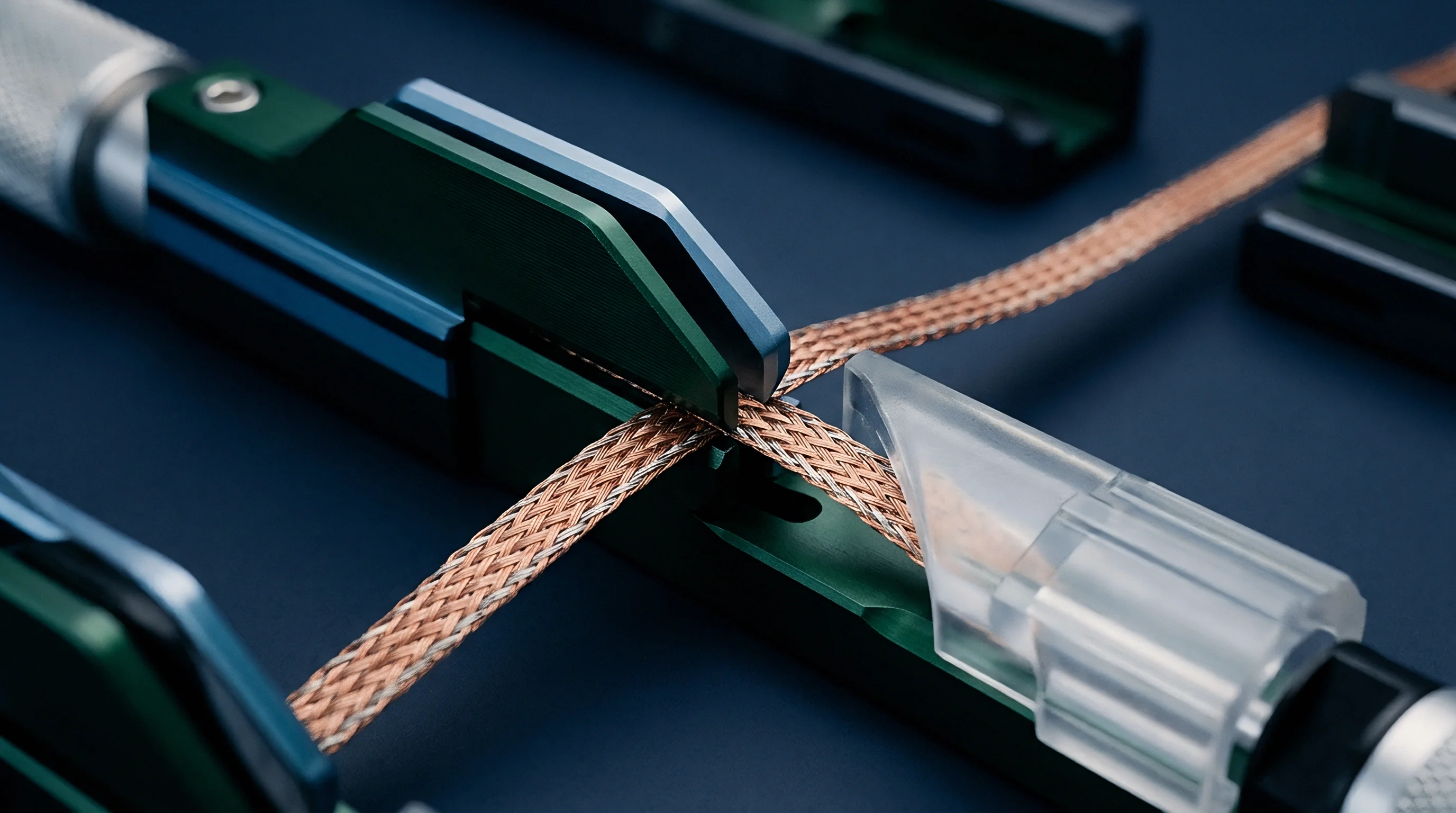
Tight mechanical routing inside ultra-compact Internet of Things housings induces permanent structural distortion across coaxial cross-sections. Micro coaxial cables advertise dynamic bend radii between three and five times their outer diameter. For a 1.13-millimeter line, this permits bending around a 4-millimeter corner post inside an injection-molded enclosure.
However, bending a coaxial structure forces the central conductor toward the inner radius of the curve. The soft fluoropolymer insulation compresses beneath the inner conductor while tensile forces stretch the outer woven braid along the exterior curve radius.
The resulting physical asymmetry produces permanent dielectric eccentricities. As the center conductor shifts off-center, characteristic impedance collapses locally. Voltage standing wave ratios rise immediately at the bend location.
Repetitive bending tests demonstrate that micro-fractures propagate across individual 44 AWG center strands within five hundred flexure cycles. These micro-cracks concentrate current density into microscopic bottlenecks, sharply driving conductor losses upward. Cold-flow creep in fluoropolymers prevents the center conductor from returning to its original concentric axis, locking in elevated attenuation profiles over product lifespans.
| Cable Format | Outer Diameter | Minimum Bend Radius | Loss at 2.4 GHz (dB/100mm) | Loss at 5.8 GHz (dB/100mm) |
|---|---|---|---|---|
| Standard Micro 0.81 | 0.81 mm | 2.0 mm | 0.31 | 0.52 |
| Standard Mini 1.13 | 1.13 mm | 4.0 mm | 0.19 | 0.31 |
| Low-Loss 1.32 Double-Shield | 1.32 mm | 4.5 mm | 0.16 | 0.27 |
| Thick Micro 1.37 | 1.37 mm | 5.0 mm | 0.14 | 0.24 |
Installation technicians must maintain smooth sweeping loops rather than sharp structural creases when securing internal antennas within confined terminal enclosures.
A gentle sweeping bend preserves line geometry while an angular crease destroys link margin.