Meaning
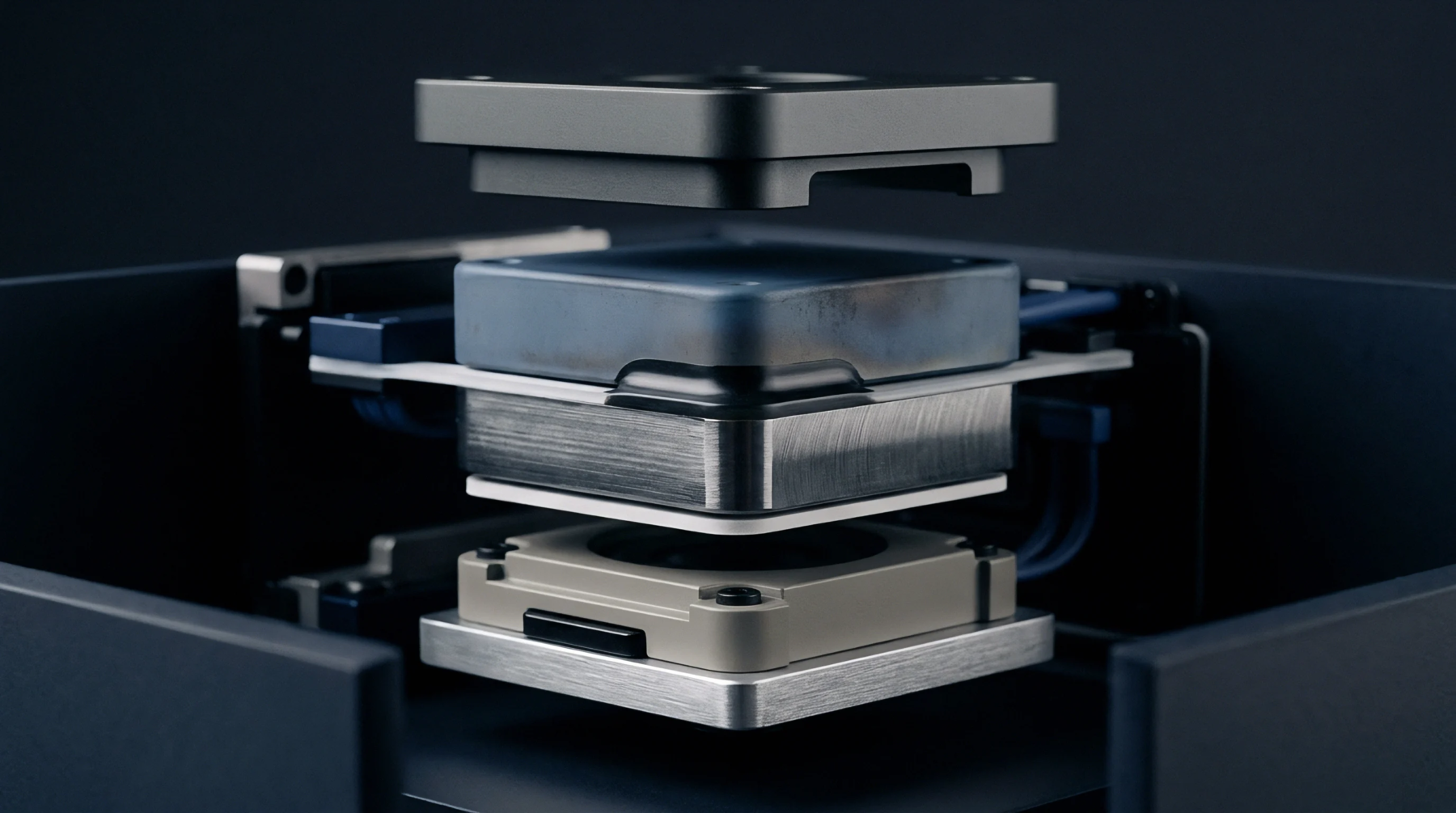
Automated test equipment relies on spring-loaded mechanical contact arrays to establish temporary electrical connections with printed circuit board test points. A pogo pin harness links test fixture instruments directly to exposed copper pads on target radio boards and controller modules. It governs signal fidelity during automated optical and functional testing on manufacturing assembly lines.
The scope excludes permanent soldered electrical connectors used in final end-user assemblies.
Contact Impedance
Spring tension forces plunger tips against target PCB contact pads to maintain low contact resistance. Integrating a pogo pin harness into bed-of-nails fixtures allows multi-channel radio frequency and power measurements without soldering wires to prototype boards. Poor plunger alignment creates high contact resistance that skews voltage measurements during factory calibration.
Fixture Alignment
Mechanical guide pins align the test fixture frame with PCB locating holes to prevent lateral needle scrubbing on target pads. Precise pogo pin harness orientation prevents probe tips from slipping off small test points onto adjacent trace lines. Misalignment damages target board solder mask layers and causes false test rejections.
Pneumatic actuators apply uniform downward force across the entire pin cluster to compress every spring probe to its target operating height.
Wear Degradation
Repeated compression cycles cause spring fatigue and tip surface contamination from flux residue. Maintaining a pogo pin harness requires periodic cleaning and cycle counting to replace degraded probes before contact resistance rises. Worn probe springs produce erratic grounding during RF power amplifier calibration tests.