Meaning
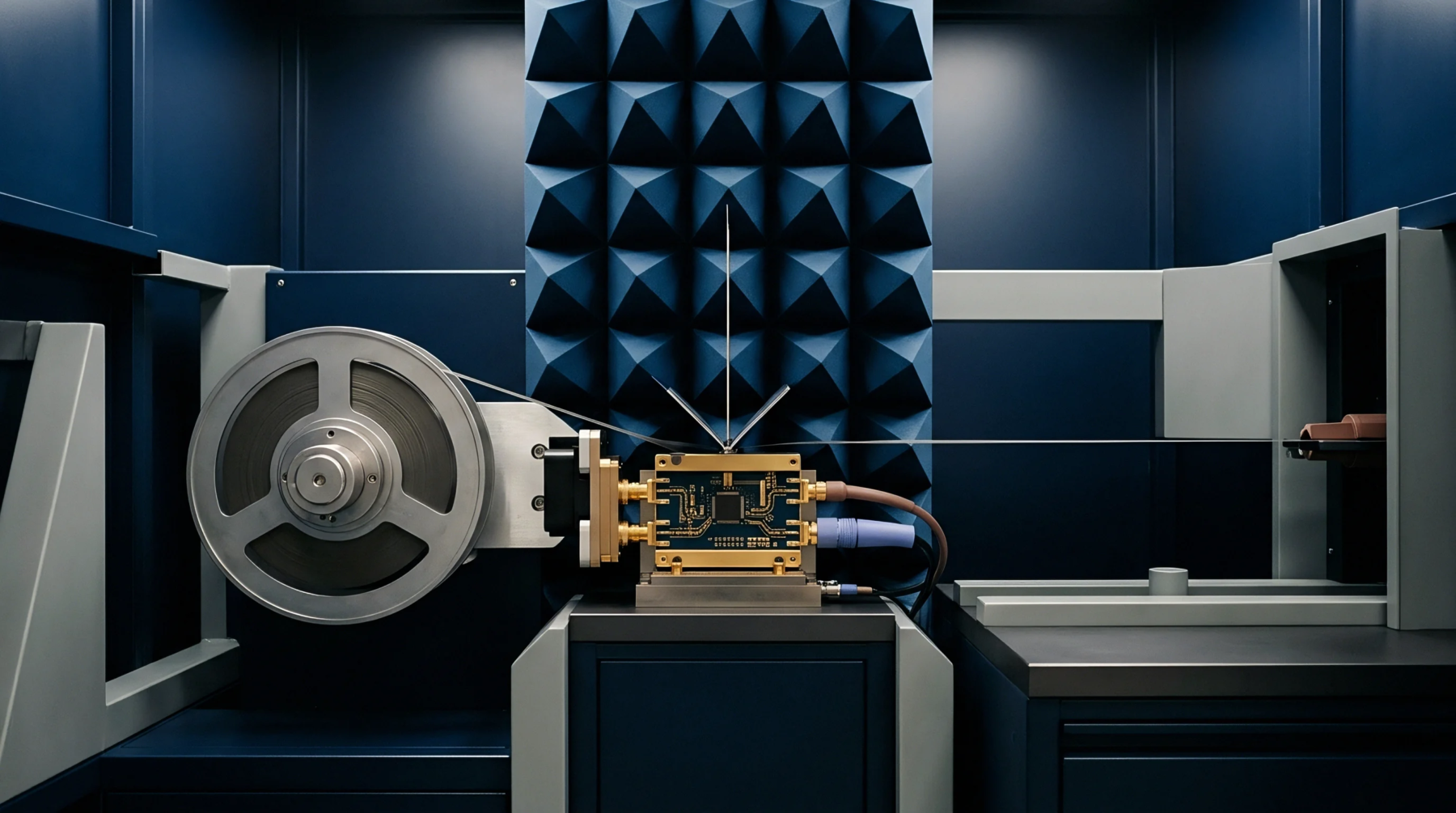
Signal power loss occurring as an electromagnetic wave propagates through a transmission medium or across a physical boundary constitutes radio frequency attenuation. This reduction in intensity occurs because the dielectric and conductive materials absorb electromagnetic energy and convert that energy into heat. Decibel units quantify the ratio between input power and output power, allowing engineers to track losses across coaxial cables, waveguides, or free space.
Designers rely on this measurement to ensure that signal levels reaching a receiver remain within the operating sensitivity range after travelling from an antenna or through internal circuitry.
Signal Budget
Managing this degradation dictates the maximum length of cabling allowed between an integrated module and an external chassis interface. Excessive loss limits the range of wireless communication and drops the signal below the noise floor of the receiver hardware. Manufacturers determine these constraints during the thermal validation phase where high temperatures increase the resistance of conductive paths and accelerate the dissipation of energy.
Engineers select materials with specific loss tangents to minimize this drop when high frequency performance is mandatory for the product application.
Integration Impact
Attenuators function as controlled components to match impedance levels or to prevent receiver saturation during high power testing sequences. Precise control of these components requires verification against a calibrated signal generator to confirm that the measured insertion loss aligns with the predicted link budget of the system assembly. Developers adjust these configurations during the initial prototyping stage to compensate for variances in connector insertion or printed circuit board trace geometry.
Component Tolerance
Standardisation bodies define acceptable levels of power reduction for various hardware categories to prevent noncompliant emissions or degraded reception in sensitive electronic equipment. Suppliers provide data sheets that specify the maximum loss per unit length for cables or insertion loss for filters at defined frequency bands. Compliance labs verify these specifications by injecting known signals at one port and recording the output at the destination to map performance across the operating spectrum.
Verified values ensure that the final product maintains consistent link performance across all manufactured units.