Dissecting Amortized Tooling and Engineering Hours from Semicustom Module Economics
Unbundling non-recurring engineering fees from unit prices protects hardware margins and guarantees access to native design databases during manufacturing scale.


Partition
Every commercial module proposal hides a boundary where paid vendor labor ends and buyer-side expense begins. Semicustom procurement bridges off-the-shelf catalog parts and bespoke custom builds. When selecting a semicustom RF or compute module, the commercial quote typically splits costs into two buckets: non-recurring engineering charges and unit piece prices.
Suppliers often bundle tooling modifications, board support package adaptations, pinout revisions, and regulatory testing into an amortized unit price. That structure masks the true unit manufacturing cost along with the actual engineering hours logged at the factory.
This landed cost model breaks down if production volumes diverge from contractual forecasts. If a buyer commits to a hundred thousand units over two years with a five-dollar surcharge per unit to recover five hundred thousand dollars in engineering and tooling, a volume shortfall exposes the buyer to retroactive recovery invoices. Conversely, exceeding that volume without an automated step-down means paying for already amortized assets in perpetuity.
Separating pure bill-of-materials cost from deferred development hours is essential to understanding real module economics.
Amortizing development overhead across unit pricing transfers production volume risk directly onto the unit margin.
Sourcing engineers evaluate the division of labour across four primary integration models:
- Turnkey module procurement keeps all board layout adjustments, passive component selection, and base firmware within the factory scope, locking the buyer out of native design databases.
- Semicustom hardware adaptation modifies baseboard geometry, shield clip placements, or edge contact pads while preserving the vendor’s core circuit architecture and certification lineage.
- Reference design licensing hands schematics, Gerber archives, and bill-of-materials definitions over to the buyer for local board fabrication under vendor review.
- White-label manufacturing supplies unbranded standard subassemblies with factory-programmed custom bootloaders, leaving testing, enclosure assembly, and host integration to downstream facilities.

Engineering Split across Sourcing Models
These scope boundaries dictate who absorbs prototype respins, impedance tuning iterations, and EMC pre-compliance test failures. In standard turnkey deals, the vendor guarantees RF parametric performance and regulatory grant validity ~ provided the host board follows vendor reference ground planes and keep-out corridors exactly. Once a buyer requests a semicustom edit, like shifting a low-noise amplifier matching network or dropping substrate layers from eight to six, the vendor bills those engineering hours back to the customer.
| Engagement Tier | Firmware Ownership | Schematic Access | Tooling Amortization Scope | Regulatory Transfer Feasibility |
|---|---|---|---|---|
| Turnkey Standard | Factory binary only | Pinout diagram and PDF | Standard production dies | Factory modular grant applies |
| Semicustom Variant | Factory base plus custom tree | PDF with masked sub-circuits | Bespoke carrier plates and shields | Class II permissive change required |
| Reference Design | Buyer owns board support modifications | Complete EDA databases | Buyer funds all fabrication tooling | Buyer conducts primary certifications |
| White-Label Build | Factory firmware with custom keys | Block diagram only | Zero custom tooling allowed | Factory grant reused with label change |
Understanding this split prevents misallocated capital. When suppliers propose waiving upfront non-recurring engineering fees in exchange for a higher piece price, they convert fixed development risk into an ongoing variable expense. Sourcing teams must evaluate whether the engineering effort represents genuinely novel development or routine parametric validation.
Suppliers maintain extensive libraries of verified circuit blocks; charging full engineering rates for minor track re-routing simply inflates vendor margin.
Failing to parse the boundary between physical component cost and deferred non-recurring engineering leaves procurement teams paying premium prices for standard catalog silicon long after tooling costs have been fully recovered.

Solder
Surface-mount radio frequency subassemblies introduce strict physical constraints during assembly. Land grid array and ball grid array pads beneath a semicustom module hide the primary mechanical and electrical interconnects between substrate and host carrier board. Re-routing high-speed traces or relocating decoupling capacitors alters the thermal mass across the package footprint.
Uneven copper distribution causes uneven heat absorption during reflow, triggering solder bridging, tombstoning of passive components, and voiding in ground terminations.
Thermal expansion coefficients frequently differ between the module dielectric and the host board. High-density interconnect substrates using bismaleimide-triazine laminate expand at different rates than standard FR-4 carrier boards during thermal cycling, placing cyclic shear stress on solder joints. When evaluating semicustom options, buyers need to check physical stack-up drawings to verify that pad geometries, solder mask defined openings, and thermal vias align with the target assembly line.
Voiding ratios exceeding fifteen percent in central ground thermal pads induce radio frequency grounding parasitics and elevate component junction temperatures.
Physical construction directly governs testability and inspection yields on the factory floor. Modifying shield geometries changes convective heat transfer across internal components. If an RF power amplifier sits next to an internal shield wall, that local heat sink slows reflow heating and creates cold solder joints beneath surface-mount parts.
Automated optical inspection cannot see through metallic shields, while standard two-dimensional automated X-ray inspection struggles to distinguish top-side substrate solder from the joints attaching the module to the carrier board.
Tooling quotes frequently include custom pallets, reflow carrier frames, and selective soldering masks required for these hybrid assemblies. When a module alters the package envelope or drops pad pitch from a standard 1.27 millimeter spacing down to 0.8 or 0.5 millimeters, defect rates climb sharply unless paste deposition is tightly controlled. Laser-cut stencils, step-down foils, and nano-coatings quickly become mandatory line tooling, adding unbudgeted capital expense.
Reflow voiding anomalies frequently stem from host layouts that depart from the reference thermal relief geometry.

Stencil
Aperture design dictates paste transfer repeatability on high-density carrier assemblies. Fine-pitch perimeter pads on dual-band wireless modules require solder paste volume control within tight margins. If a semicustom variant moves outer castellated ground pads closer to high-speed differential pairs, bridging risks multiply during reflow.
Stencil precision ~ whether electroformed or laser-cut nickel ~ sets baseline assembly yields before components ever reach the pick-and-place gantry.
Altering module land patterns shifts the aperture area ratio. Paste release efficiency drops sharply when the ratio of aperture width to foil thickness falls below 0.66. When a semicustom package combines fine-pitch perimeter pads with large central thermal pads, a uniform stencil thickness creates opposing failure modes.
Standard 120-micrometer stencils deposit too much paste on 0.5-millimeter pitch signal pads, causing bridges, while starving large central ground pads that need heavy coverage. Resolving this requires step-stencil tooling, where localized relief pockets are milled or electroformed into the foil.
Area ratios below 0.66 cause erratic solder volume deposition and post-reflow functional defects.
Step-stencils add lead time and maintenance overhead. A stepped foil with thirty-micrometer step-down pockets across RF sub-zones costs four to five times more than a standard planar laser-cut stainless steel stencil. Stepped foils also interfere with automated squeegee travel, causing premature blade wear and uneven paste wiping across adjacent components.
Production teams have to weigh these tooling costs against the expected benefits of pad relocations.
Ultimately, assembly yields reflect how accurately mechanical tooling definitions match the physical board layout.


Hours
Non-recurring engineering invoices from module vendors often group distinct technical disciplines into opaque billing entries. A typical project spans baseband layout, RF matching network simulation, driver integration, regulatory testing, and test jig fabrication. With hourly rates ranging from one hundred twenty to two hundred eighty dollars depending on geography and specialized RF capabilities, buyers need itemized hours tied to clear technical deliverables.
Software and firmware adaptation consumes most unscrutinized engineering hours. Board support package work for a semicustom microcontroller or SoC module includes pin multiplexing, device tree edits, clock tree calibration, and PMIC driver updates. Routine bootloader alterations that simply disable unused peripheral interfaces or adjust UART debug assignments are frequently billed at inflated rates.
Sourcing teams should audit software estimates against standard driver porting benchmarks.

Deliverables and Verification Criteria
Every engineering charge should link to a tangible file deliverable, a git commit, or a lab test report. The table below outlines standard task allocations, realistic labor ranges, and the verification required to clear milestone payments.
| Task Category | Engineering Scope | Realistic Hours | Mandatory Verification Deliverable |
|---|---|---|---|
| Schematic Adaptation | Pin mapping and power rail changes | 20 – 45 | Native Altium or OrCAD schematics with ERC log |
| PCB Layout and Stack-up | Signal routing, RF stripline, impedance | 40 – 90 | Gerber RS-274X or IPC-2581 files and stack-up report |
| RF Matching and Tuning | Smith chart matching, VNA calibration | 35 – 75 | Touchstone s2p files and calibrated return loss plots |
| Board Support Package | Device tree and peripheral driver patches | 50 – 120 | Git repository branch, build container, boot log |
| Regulatory Pre-Scan | EMC, spurious emissions, SAR check | 30 – 60 | Accredited laboratory chamber measurement report |
| Production Test Firmware | ATE test scripts, flashing binaries | 40 – 80 | Automated test sequencer code and CLI documentation |
Test fixture development accounts for another large block of engineering hours. Suppliers routinely quote eighty to one hundred fifty hours for bed-of-nails test jig design and functional test scripting. Sourcing managers must confirm whether this equipment remains vendor property or transfers to the buyer.
If the customer pays for custom pogo-pin fixtures, pneumatic clamps, and RF shielding enclosures, those physical assets and test scripts belong on the buyer’s balance sheet.
Suppliers frequently withhold raw native source files, providing only compiled binaries and PDF schematics. This creates vendor lock-in. If the buyer later moves production to a second-source contract manufacturer, the lack of native EDA databases and reproducible firmware build scripts forces them to pay a second NRE fee to rebuild the design assets.
Contracts should explicitly require delivery of all native files before final NRE payments are disbursed.
Development contracts must include an IP assignment clause guaranteeing the transfer of layout databases, build scripts, and test sequences once non-recurring engineering fees are paid.

Escrow
Retaining software intellectual property is the main way module vendors maintain leverage over buyers. Even when a buyer pays for custom firmware modifications, vendors routinely keep core microcode, radio calibration algorithms, and secure bootloader keys. If the vendor goes bankrupt, drops the product line, or raises piece prices, the customer cannot update firmware or shift production without access to the source code.
Escrow agreements protect against this risk by holding source trees, toolchains, build scripts, and cryptographic keys with a neutral third party. A proper firmware escrow package must contain everything required to produce a bit-for-bit reproducible build from bare metal. Contracts should list the required assets and set deposit schedules tied to version releases.
An escrow deposit lacking the exact containerized compiler environment and private signing keys fails to protect against operational obsolescence.
Software escrow packages must incorporate these essential components:
- Source code repositories with full version histories, branch logs, submodules, and library dependencies needed for target compilation.
- Containerized build environments containing exact compiler versions, linker scripts, makefiles, and environment variables configured for deterministic builds.
- Binary patch utilities and memory mapping tables used to calibrate radio trim values and MAC address offsets during board bring-up.
- Cryptographic signing keys and hardware security module configurations needed to sign secure bootloader images.
Escrow verification is a routinely overlooked operational step. Buyers frequently sign agreements without checking what was actually deposited. A proper deposit audit requires an engineer to load the package onto a clean, air-gapped machine, run the build script, flash the binary onto hardware, and verify that it passes standard regression tests.
Without this check, deposits often contain broken archives, missing header files, or obsolete branches that are useless in a crisis.
Release terms specify when the escrow agent turns assets over to the buyer. Standard triggers include vendor bankruptcy, breach of supply contracts, failure to patch security vulnerabilities within agreed timelines, or end-of-life notices issued without adequate lifetime buy windows. Defining tight, clear release triggers allows the buyer to support fielded hardware across its full lifecycle.
The main practical challenge is keeping third-party escrow verification in sync with rapid firmware updates across continuous integration pipelines.

Reversion
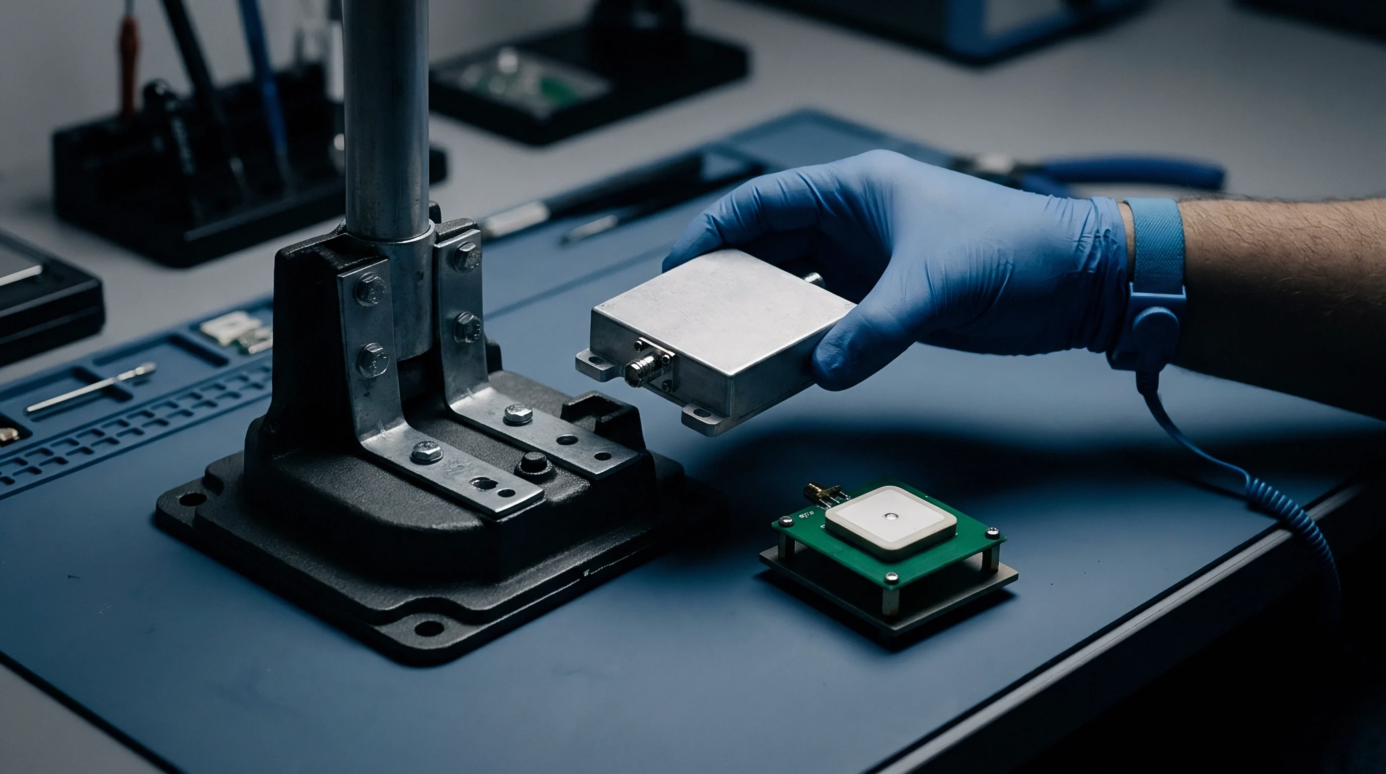
Moving from a semicustom module back to an off-the-shelf part ~ or taking the leap to a full chip-on-board design ~ is a critical strategic pivot. At modest volumes, semicustom modules balance development speed against size constraints. But as production scales into hundreds of thousands of units, cumulative price premiums and unrecovered tooling make modules uncompetitive against discrete designs integrated directly onto the main board.
Finding the economic crossover point requires continuous financial modeling across hardware revisions. A discrete chip-down implementation demands substantial upfront NRE for eight-layer impedance-controlled layouts, high-frequency RF simulation, and full regulatory certifications across FCC, CE, ISED, and MIC jurisdictions. However, discrete silicon drops the raw bill-of-materials cost far below packaged module prices.
Calculating the crossover volume pinpoints the right manufacturing milestone to execute the redesign.

Lifecycle Cost Comparison
The financial picture changes as production ramps over time. Semicustom modules lower initial entry costs but drag on unit margins through embedded vendor markups. Discrete integration requires high upfront capital, but delivers the lowest marginal cost once high-volume manufacturing takes over.
| Cost Component | Turnkey Module | Semicustom Module | Discrete Chip-Down Design |
|---|---|---|---|
| Initial Upfront NRE | $0 | $45,000 | $180,000 |
| Tooling and Fixtures | $5,000 | $25,000 | $60,000 |
| Regulatory Certification | $0 (Inherited) | $18,000 (Permissive) | $75,000 (Full Primary) |
| Unit Bill of Materials | $12.50 | $10.80 | $6.20 |
| Embedded Amortization | $0.00 | $1.50 | $0.00 |
| Total Production Cost | $2,505,000 | $2,548,000 | $1,555,000 |
Reversion requires careful management of board layout and RF behavior. Removing a module to place discrete transceivers directly on the carrier board means the engineering team must design all high-frequency ground return paths, decoupling loops, and impedance-matched transmission lines previously handled inside the module shield. Layout parasitics once managed internally by the vendor suddenly dictate radiated emissions, receiver sensitivity, and harmonic distortion.
Engineering teams must evaluate the regulatory impacts of design reversion early in planning. Semicustom modules often reuse existing modular approvals, limiting compliance costs to Class II permissive changes. Moving to a full chip-down architecture invalidates modular grants completely, requiring primary intentional radiator testing across all operating bands.
Sourcing managers should budget sixty to ninety days for chamber and anechoic testing during the transition.
Manufacturing must also manage supply chain lead times and minimum order quantities when buying discrete silicon directly from suppliers rather than bundled modules. Handling dozens of individual line items, moisture sensitivity ratings, and tape-and-reel packaging adds real inventory overhead. Production schedules have to accommodate these extra variables to keep assembly lines running smoothly during the transition.