PCB Counterpoise Truncation Causes Radiated Efficiency Drop and Pattern Distortion
Truncating PCB ground planes collapses antenna radiation resistance, creates deep directional nulls, and forces RF return currents into noisy peripheral traces.


Current
Every quarter-wave trace or printed inverted-F radiator forms one half of an asymmetric dipole system. The printed trace provides the driven element, while the system ground pour serves as the counterpoise. High-frequency RF energy does not end at the antenna feedpad; conduction charges circulate across the entire surface of the ground copper to complete the displacement circuit.
When a layout engineer truncates this counterpoise below one quarter of a free-space wavelength, the physics of the radiator changes abruptly.
The antenna is only half the circuit. RF displacement currents crossing the dielectric air gap must find a return path of equal magnitude on the ground plane. When the conductive plane lacks sufficient physical dimensions, surface current density piles up at the ground boundaries, creating localized phase shifts that prevent proper electromagnetic field formation.
A quarter-wave radiator without an equal counterpoise forces displacement currents into chassis wiring, battery traces, and attached sensor cables.
High-frequency surface charges concentrate along the immediate periphery of the copper pour closest to the feedpoint. As edge boundaries move closer to the feed point, the effective current loop area shrinks, driving up high-frequency ohmic dissipation across the outer copper edges. Peripheral traces begin carrying unintended RF currents, turning control lines and sensor traces into active radiators that leak energy at uncontrolled angles and degrade overall link stability.
- Edge current crowding develops when ground boundaries sit within 0.1 wavelengths of the antenna feed, causing severe localized resistive losses along board peripheries.
- Common-mode cable excitation forces RF currents down attached power harnesses and external sensor leads, generating unpredictable phase cancellations across the room.
- Chassis ground coupling transfers reactive currents to adjacent metal shields, pulling the operational resonant point far above the intended band allocation.
- Phase-delayed counterpoise radiation creates destructive interference between the driven element and ground edges, collapsing the primary radiated wavefront.

What Current Density Remains along Choked Ground Edges?
Current distribution along a foreshortened plane loses its smooth sinusoidal decay. On a counterpoise spanning at least 0.3 wavelengths, RF current density rolls off predictably toward the far edge. Truncating that length forces the wave to reflect from the boundary before its phase can mature.
Standing waves form across the truncated ground foil, elevating the reactive near field and trapping energy that would otherwise escape into free space.
Displacement currents diverted into battery leads alter impedance matching and pull receiver sensitivity thresholds downward through elevated baseband noise. Shrinking the grounding mirror forces the feedline and battery harness to radiate instead of the antenna.

Copper
A ground plane dimension below 0.4 wavelengths across forces the antenna input resistance down toward single-digit ohms. Radiation resistance defines how effectively an antenna converts feedpoint current into radiated fields. In an ideal quarter-wave monopole over an infinite ground plane, radiation resistance measures roughly 36.5 ohms.
As the counterpoise contracts, that figure drops precipitously toward 5 ohms or less, while the ohmic loss resistance of the copper remains constant.
Input impedance drops below ten ohms. When radiation resistance drops to values comparable to the equivalent series resistance of matching components and copper traces, radiated efficiency plunges and conduction losses turn transmitter power directly into board heat. An inverted-F antenna tuned for 915 MHz on a full 100 mm ground plane exhibits an efficiency of 75 percent.
Truncating that copper plane to 30 mm drops the efficiency below 18 percent, introducing a direct 6.2 dB attenuation to the transmitter output before the wave even enters the path.
Operating an 868 MHz monopole over a 35 mm truncated plane drops radiation resistance from 32 ohms to 6 ohms, imposing a 5.8 dB efficiency loss.
Mismatched ports and narrow traces turn RF energy directly into heat. Because matching networks cannot differentiate between productive radiation resistance and unproductive loss resistance, a network analyzer may show an acceptable return loss of -15 dB while the board radiates almost nothing.
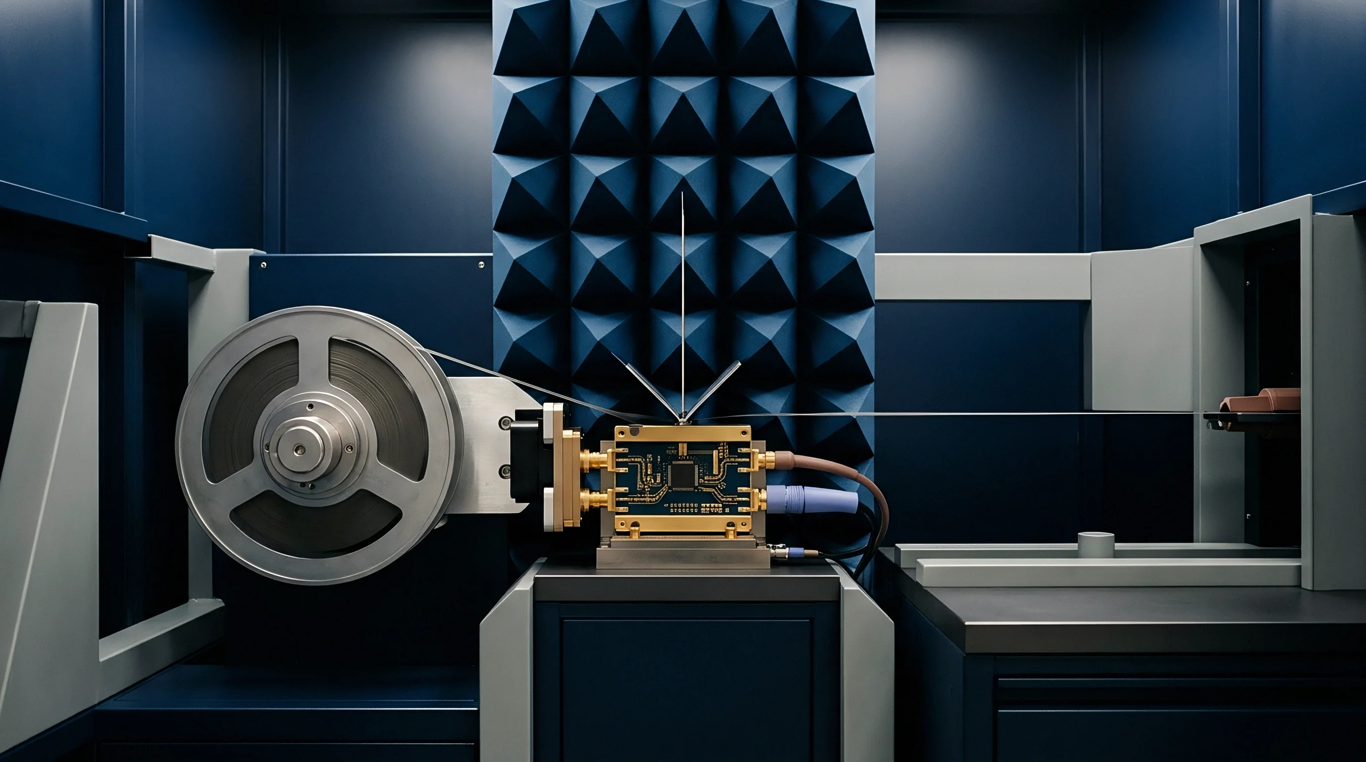
- Mount the bare prototype PCB inside an anechoic chamber on a low-permittivity foam pedestal positioned at least 1.5 meters from all wall absorbers.
- Connect calibrated semi-rigid coaxial cabling equipped with ferrite bead chokes spaced at 0.1-wavelength intervals along the exterior jacket to block cable-borne currents.
- Record the complex S11 reflection coefficient from 700 MHz to 2.7 GHz using a calibrated two-port vector network analyzer at a sweep resolution of 100 kHz.
- Perform a complete 3D spherical scan at 15-degree angular steps across both horizontal and vertical polarizations to capture total radiated power.
- Calculate total radiated efficiency by integrating spherical power patterns and dividing the sum by net delivered power at the antenna connector.
How Far Does Ground Plane Shrinkage Suppress Gain?
Total radiated power collapses when conduction losses overtake the diminished radiation resistance. In sub-gigahertz IoT deployments using 868 MHz or 915 MHz LoRaWAN and NB-IoT protocols, physical enclosure constraints frequently force counterpoise lengths below 40 mm. Because a quarter-wavelength at 915 MHz measures 82 mm in air, a 40 mm counterpoise represents less than an eighth of a wavelength.
Radiated efficiency drops by 6 to 10 dB in this geometry, forcing transmitters to boost output power to hold link margin.
| Frequency Band | Counterpoise Length | Wavelength Fraction | Radiation Resistance | Radiated Efficiency | Link Penalty |
|---|---|---|---|---|---|
| 433 MHz ISM | 50 mm | 0.07 λ | 2.1 Ω | 6.5 % | -11.9 dB |
| 868 MHz SRD | 40 mm | 0.12 λ | 5.8 Ω | 18.2 % | -7.4 dB |
| 915 MHz ISM | 45 mm | 0.14 λ | 7.4 Ω | 23.5 % | -6.3 dB |
| 915 MHz ISM | 90 mm | 0.27 λ | 28.6 Ω | 71.0 % | -1.5 dB |
| 2.4 GHz ISM | 25 mm | 0.20 λ | 18.2 Ω | 52.0 % | -2.8 dB |
| 2.4 GHz ISM | 50 mm | 0.40 λ | 34.1 Ω | 84.5 % | -0.7 dB |
Truncated ground planes compress operating bandwidth. The operational Q-factor of an electrically small radiator increases sharply as counterpoise dimensions decline. A high Q-factor narrows the impedance bandwidth, meaning slight production variations in board substrate dielectric constant shift the return loss curve completely outside the operational band.
Production yields drop when small fabrication tolerances detune the entire RF front end. Inserting ETSI EN 300 220-1 subclause 5.2.2 limits into the procurement agreement obligates the ODM to supply radiated spherical scans rather than conducted bench measurements.


Null
Asymmetrical counterpoise boundaries alter the local phase relationship between orthogonal electric field vectors. When an antenna sits on a balanced, extensive ground plane, radiation patterns remain largely toroidal, offering predictable omnidirectional coverage in the azimuth plane. Truncating the ground plane on one side or cropping it to fit an asymmetric enclosure breaks this azimuthal uniformity.
Deep pattern notches drop packets instantly. The physical edge of the truncated copper acts as a secondary radiator with an altered phase. Radiation from this foreshortened edge combines constructively in select directions and destructively in others, pulling the main pattern lobe toward the bulk of the remaining copper.
Deep pattern nulls appear on the truncated side, creating blind spots where antenna gain drops by 12 to 20 dB relative to peak values.
Azimuthal circularity degrades by more than 10 dB when counterpoise width drops below 0.25 wavelengths, pulling the primary radiation lobe toward the board center.
Standard benchtop power meters connected to coaxial pigtails can confirm that a transmitter delivers +14 dBm, yet an assembled unit placed at a specific angle fails to link with a gateway fifty meters away. The radio operates correctly, but the pattern distortion creates a spatial void that conducted tests cannot see.

Polarization Skew and Vector Tilt
Cross-polarization purity deteriorates rapidly when counterpoise asymmetry forces return currents to flow along diagonal paths. Monopole and IFA designs depend on linear vertical polarization. In a truncated PCB layout, displacement currents turn sharp corners around ground keep-outs, battery connectors, and display cutouts.
These angled currents generate a substantial horizontal cross-polarized field component.
Cross-polarization discrimination drops from a standard 18 dB down to 3 dB. When a vertically polarized base station antenna receives this skewed wavefront, polarization mismatch imposes an immediate 3 dB to 6 dB penalty. If the remote sensor rotates relative to the gateway, link degradation compounds.
The system loses line-of-sight range simply through structural tilt in the radiated electric field vector.
| Aspect Ratio (L:W) | Ground Area | Azimuth Peak Gain | Deepest Null Depth | Cross-Pol Isolation |
|---|---|---|---|---|
| 1:1 (Symmetric) | 8100 mm² | +1.8 dBi | -2.1 dBi | 19.5 dB |
| 2:1 (Rectangular) | 4050 mm² | +0.4 dBi | -6.8 dBi | 12.2 dB |
| 4:1 (Elongated) | 2025 mm² | -1.2 dBi | -11.4 dBi | 6.4 dB |
| 6:1 (Truncated Stub) | 1350 mm² | -3.5 dBi | -17.8 dBi | 2.1 dB |

Radiation Lobes across Asymmetric Boundaries
Truncating a rectangular ground pour along one axis pulls the primary radiation beam toward the longest remaining metallic path. In an asset tracker with a narrow 20 mm board width and a 70 mm length, the antenna does not direct energy perpendicular to the board face. The beam tilts 35 degrees toward the bottom of the enclosure, sending energy into the ground or toward adjacent mounting structures.
With the feedline acting as an unintended radiator, transmitting to a gateway broadside to the unit can drop the signal into a deep 14 dB pattern notch, an effect that is often mistaken for fixture reflections off chamber cables rather than recognized as genuine board distortion.

Range
Field performance collapses when a link encounters spatial nulls coupled with elevated total radiated losses. Range equations in module datasheets rely on line-of-sight propagation over free space with isotropic radiators. Real operating environments involve log-distance path loss, multipath fading, and variable spatial orientation.
When an engineer truncates a ground plane, both the total energy and the directional pattern suffer simultaneously.
Link margin absorbs initial mismatch loss. A typical indoor sub-GHz link budget assumes a 15 dB fade margin to combat multipath and wall attenuation. If ground plane truncation introduces a 6 dB efficiency penalty and the device sits in an orientation that aligns with an 8 dB pattern null, 14 dB of that fade margin vanishes instantly.
The link budget retains only 1 dB of reserve. A moving person or closed metal door will sever the connection entirely.
Take an asset tracker operating at 915 MHz using LoRa modulation at Spreading Factor 7 with a 125 kHz bandwidth. Transmit power is configured to +14 dBm. The gateway features an omnidirectional antenna with +3 dBi gain and a verified receiver sensitivity of -123 dBm.
Under ideal planar counterpoise conditions, the tracker antenna provides +1.5 dBi peak gain and 70 percent radiated efficiency (-1.55 dB), yielding an Effective Isotropic Radiated Power of +13.95 dBm. The available link budget equals 140 dBm, which translates to 2.4 kilometers in open urban terrain with a path loss exponent of 3.0.
Assume the tracker PCB counterpoise is truncated from 90 mm down to 35 mm to fit inside an injection-molded key fob enclosure. Radiation resistance drops to 5.2 ohms, dragging radiated efficiency down to 17 percent (-7.7 dB). In addition, pattern distortion introduces a 12 dB null in the direction facing the gateway, reducing antenna gain in that vector to -10.5 dBi.
The resulting EIRP in that direction drops from +13.95 dBm down to -4.2 dBm. The link budget contracts from 140 dBm to 121.8 dBm.
Path loss compounds in non-line-of-sight environments. In an urban terrain governed by a path loss exponent of 3.0, an 18.2 dB link budget reduction slashes the achievable communication range by a factor of four. The device communicates reliably across only 600 meters instead of the planned 2400 meters.
To overcome dropped packets caused by pattern nulls, firmware confirmation loops execute repeated retries. A LoRaWAN tracker that sends three uplinks per failed transmission triples its radio on-time. At +14 dBm output, power amplifier current draw reaches 32 milliamperes for 60 milliseconds per packet.
Tripling transmission attempts drains a standard 1200 mAh lithium-thionyl chloride battery in 14 months instead of the targeted 48 months.
- Transmit power overhead must be evaluated against local regulatory ceilings; boosting power by 6 dB to recover truncation loss can breach FCC Part 15.247 field strength limits.
- Receive sensitivity degradation occurs when unshielded microcontrollers inject broad-spectrum digital noise straight into the truncated ground plane, raising the receiver noise floor.
- Battery internal resistance increases under cold operating conditions, causing supply voltage dips when high current draws are sustained during repeated packet retransmissions.
- Gateway density requirements multiply across an installation zone when field nodes operate with deep pattern notches, driving up total infrastructure deployment costs.
Uncompensated radiated loss drains battery reserves through constant packet retransmissions and halves the serviceable deployment radius across real terrain.

Redesign
Engineers restore electrical balance in volume-constrained devices through discrete capacitive loading and bent-counterpoise geometries. When board dimensions cannot accommodate a standard quarter-wave ground plane, physical workarounds must provide the missing electrical length. Adding dedicated ground flex circuits or folding copper pours along the interior walls of a plastic chassis expands the effective counterpoise area without increasing PCB surface footprint.
Chassis screws and metal enclosure panels can shift resonant frequencies unless ground extensions maintain low-inductance connection points. A single thin ground wire or spring finger exhibits 2 to 5 nanohenries of parasitic inductance, which chokes RF currents at 915 MHz or 2.4 GHz. Broad grounding gaskets or multi-point perimeter contacts distribute the return currents evenly across available metal structures, mitigating localized current crowding.
Expanding counterpoise area through chassis-mounted flex foils recovers up to 4.5 dB of radiated efficiency in volume-constrained sub-GHz trackers.
Layout modifications must be validated through passive and active anechoic testing. S-parameter reflection sweeps on a bench network analyzer fail to capture pattern distortion and radiated efficiency loss. A design can show a perfect 50-ohm match across the band while failing entirely in the field due to spatial nulls and internal dissipation.

Topological Remedies for Compact Enclosures
Balancing the dipole structure directly solves counterpoise starvation. Implementing an integrated balanced dipole or printed loop antenna removes the system ground plane from the radiation mechanism. Loop antennas respond primarily to magnetic near fields, making them less sensitive to ground edge truncation and nearby human body effects.
Loop radiators carry their own operational trade-offs. They exhibit narrow impedance bandwidths and lower peak gains than full-sized monopoles, requiring precision tuning components with tight tolerances. However, they preserve stable radiation patterns across asymmetric circuit boards, eliminating the deep 15 dB nulls that plague truncated monopoles.

Qualification Gates for Truncated Boards
Procurement teams must enforce strict RF performance metrics before approving volume tooling. Relying on module vendor reference designs is risky when the host carrier board truncates the recommended counterpoise dimensions. A module rated for +20 dBm output cannot compensate for an antenna system that dissipates 80 percent of its input energy as heat.
Qualification files must document Total Radiated Power and Total Isotropic Sensitivity across full 3D spherical rotations. Contract specifications should set clear acceptance floors for minimum radiated efficiency and maximum allowable pattern null depth across all operational bands. The exact boundary where dynamic hand capacitance overrides the radiation penalty of an artificially truncated planar counterpoise remains unmodeled in standard simulation packages.