Quartz Resonator Surface Mass Loading and Aging Mechanisms
Acoustic surface mass deposition and mounting strain drive irreversible frequency offsets that degrade wireless receiver sensitivity and collapse link margins.


Film
Reference oscillators establish the spectral boundary for every packet transmitted over industrial and commercial radio links. For dense frequency-shift keyed and orthogonal frequency-division multiplexed links, slight physical alterations on the quartz blank pull the carrier off center. Early in an oscillator’s operating life, frequency displacement comes down mainly to foreign matter gathering on or leaving the active metallized area.
As trace organic residues, moisture, or outgassed assembly products collect on the electrode, they add thickness to the acoustic cavity. The acoustic shear waves now propagate across greater mass, dragging down the fundamental resonant frequency.
Under uniform, rigid thin-film conditions, the classical Sauerbrey equation describes this response. For an AT-cut quartz plate operating in thickness-shear mode, the drop in resonant frequency scales directly with the added mass per unit area:
Δf = – (2 f0^2 / (A (ρq μq)^0.5)) Δm
In this expression, f0 is the fundamental resonant frequency, A is the active vibrating electrode area, ρq is quartz density at 2.648 g/cm³, μq is the shear modulus of AT-cut quartz at 2.947 x 10^11 g/(cm·s²), and Δm is the added mass. A standard 32 MHz fundamental crystal designed for 2.4 GHz Bluetooth Low Energy or sub-GHz transceivers has an active vibrating diameter under one millimeter. On an electrode that small, a single monomolecular layer of condensed moisture or siloxane polymer adds only several nanograms of mass, yet that minuscule loading pulls the frequency down by more than 5 to 10 parts per million.
A surface mass deposition of two nanograms shifts a 32 MHz fundamental crystal by six parts per million.
Inside hermetic packages, gold and silver electrodes behave quite differently over time. Silver metallization gives low electrical resistance and bonds well, but it reacts quickly with traces of atmospheric sulfur and halogens, building up tarnish films that add permanent mass. Gold resists oxidation entirely, but requires an adhesion sublayer ~ usually chromium or titanium.
When seam sealing or glass fritting runs hot, these adhesion metals diffuse along gold grain boundaries up to the exposed face. Once at the surface, the migrated metal oxidizes in the cavity headspace, forming patchy oxide films that add mass and drive up mechanical damping.

Electrode Metallization and Sorption Dynamics
Residual gases trapped in the package produce ongoing sorption cycles as temperatures shift. Ceramic surface-mount device enclosures sealed with gold-tin preforms hold varying internal pressures determined by the seal furnace atmosphere. Meanwhile, conductive epoxy used to mount the quartz blank continues outgassing volatile organic compounds, steadily loading the active area over time.
| Electrode Material | Adhesion Layer | Primary Contaminant Affinity | Typical Mass Shift Rate | Electrode Thickness Range |
|---|---|---|---|---|
| Pure Gold | Chromium (10-20 nm) | Hydrocarbons and siloxanes | 0.2 to 0.8 ppm/year | 80 to 150 nm |
| Pure Gold | Titanium (15-25 nm) | Trace organic vapors | 0.1 to 0.5 ppm/year | 70 to 120 nm |
| Silver | None | Atmospheric sulfur and halogens | 1.0 to 3.5 ppm/year | 100 to 200 nm |
| Aluminum | None | Moisture (spontaneous oxide growth) | 0.5 to 1.8 ppm/year | 100 to 250 nm |
During reflow, polyimide and silicone mounting adhesives shed short-chain polymers into the cavity headspace, which then settle onto the active vibrating area. This mass loading climbs steeply at lower temperatures as organic vapors condense onto the gold. The frequency drops when a board moves into cold outdoor air, then recovers as the ambient warms up during the day.
Initial downward frequency drifts are often treated as benign settling, but they just as readily point to severe outgassing contamination.

Strain
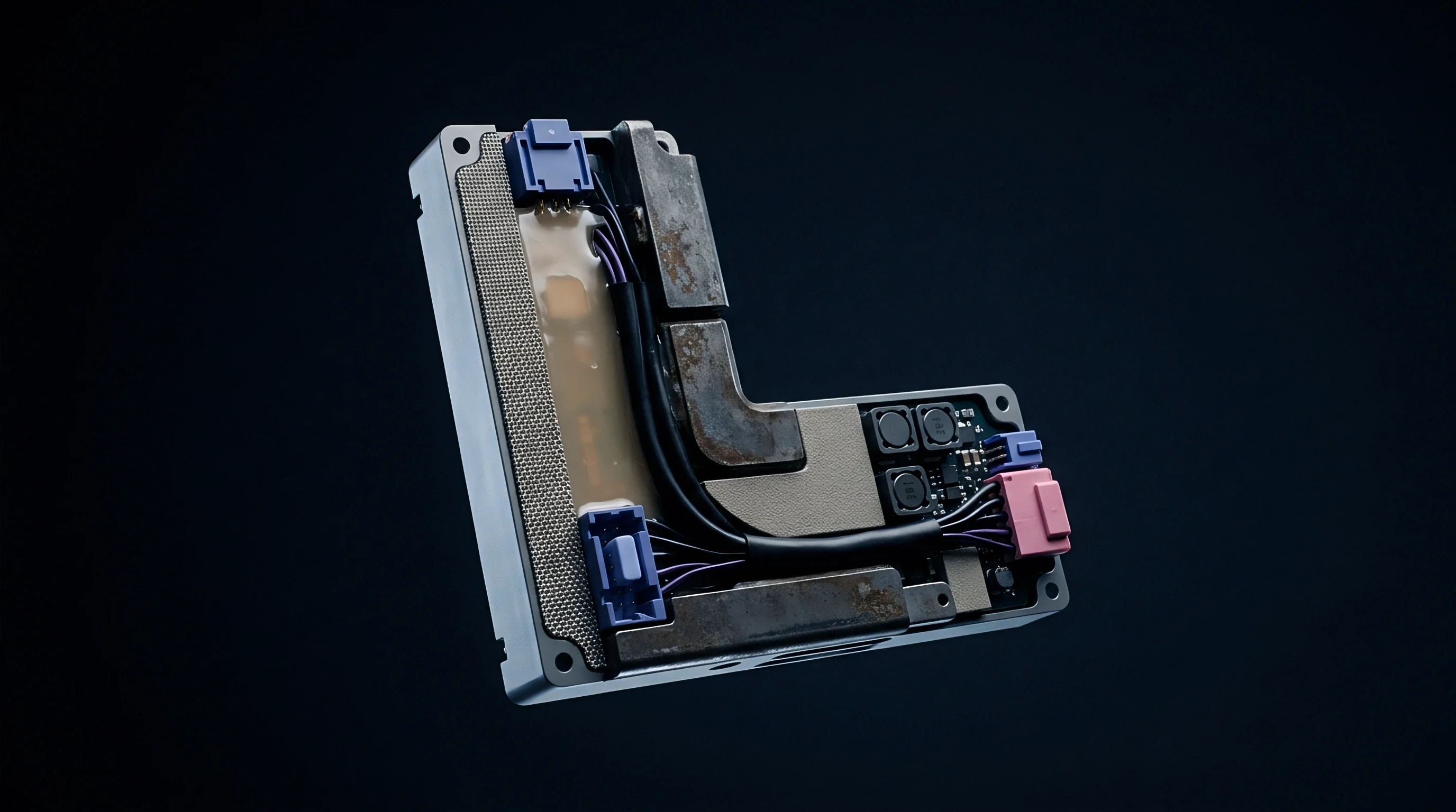
Mounting structures channel static mechanical loads straight into the active vibrating region of the quartz blank. Typically, conductive epoxy dots anchor the blank at two or four peripheral points on metallized ceramic pedestals. During assembly, lead-free reflow profiles peaking between 245 and 260 degrees Celsius trigger mismatched thermal expansion among the quartz, the conductive epoxy, and the alumina ceramic package.
AT-cut quartz expands anisotropically ~ 13.7 x 10^-6 per Kelvin parallel to the atomic x-axis versus 7.48 x 10^-6 per Kelvin perpendicular to the z-axis ~ while the alumina package expands at roughly 6.5 x 10^-6 per Kelvin.
As the assembly cools, that expansion mismatch locks residual stress into the quartz. Stress gradients across the active area alter acoustic wave velocities through the third-order elastic constants of the material: compression along the crystallographic x-axis drives the resonant frequency up, while tension pulls it down. Over subsequent months, the polymer chains in the conductive adhesive slowly relax, bleeding off some of that locked stress and drifting the frequency independently of any surface mass loading.
Mechanical Stress Profiles across Package Geometries
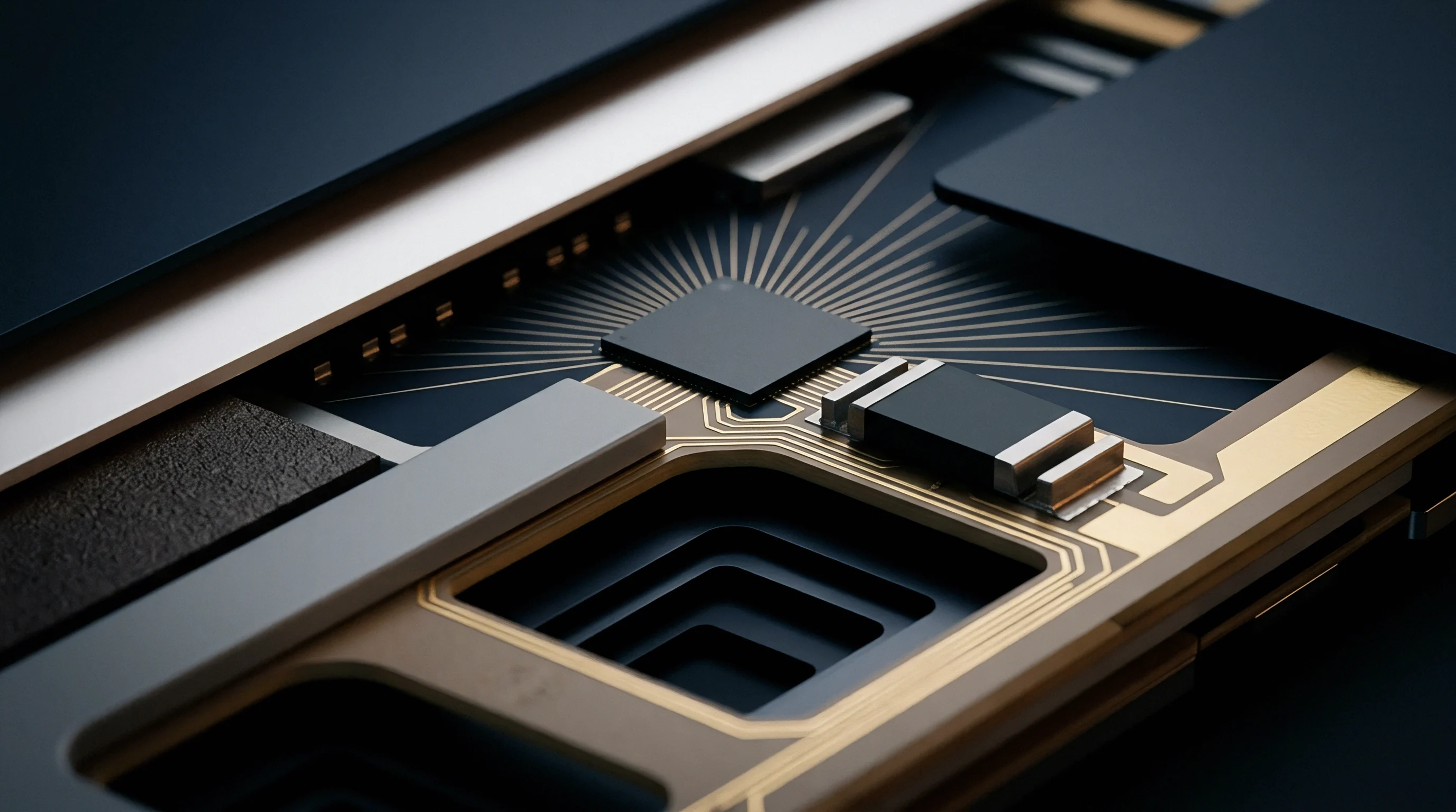
Miniaturization forces package stress closer to the acoustic path. In older 5.0 x 3.2 mm packages, the mounting joints sit well clear of the central electrode. In 2.0 x 1.6 mm and 1.6 x 1.2 mm packages, however, the conductive epoxy lies less than 300 micrometers from the edge of the vibrating electrode.
Because the mounting stress overlaps directly with the thickness-shear energy distribution, small packages react sharply to circuit board flexure and uneven solder volumes.
Board flexure from de-paneling, torque on mounting screws, or thermal cycling imposes bending moments across the solder joints. Those loads warp the ceramic base, passing lateral forces up through the internal pedestals into the quartz. Deflecting a standard 100 mm board span by just 0.5 mm can produce a transient 2 to 4 ppm frequency shift in an ultra-miniature resonator.
Circuit assembly flexure transfers mechanical force across package pedestals to induce instantaneous carrier offsets.
Over-molding creates severe compressive loading. When low-power radio modules are encapsulated via epoxy transfer molding for environmental sealing, high resin pressures bear down directly on the package exterior. As the molding compound cures, shrinkage forces the ceramic walls inward, reducing internal clearances and driving long-term frequency drift.
Crystal manufacturers counter this with reinforced seam-weld lids engineered to withstand mold clamping pressures up to 80 bar.
- Epoxy curing produces initial volume shrinkage of one to three percent, establishing baseline mounting tension across internal ceramic pedestals.
- Reflow thermal excursion softens polymer bonds at 250 degrees Celsius, letting the blank shift under surface tension.
- Cooling contraction locks in anisotropic compression along crystallographic axes because the materials contract at different rates.
- Viscoelastic relaxation bleeds off structural strain over thousands of operating hours, shifting resonant frequency steadily upward.
When local reference drift overshoots receiver carrier tracking limits, synthesizers on narrow channel plans lose lock. In narrowband cellular links, accumulated strain drift can push the reference past the demodulator capture window, dropping downlink packets entirely and triggering reconnect loops that drain the battery.

Lattice
Baseline stability across the life of an oscillator depends heavily on internal crystal defects. Both natural and synthetic quartz carry point defects, interstitial impurities, and growth dislocations left behind by the hydrothermal process. Aluminum cations (Al³⁺) substitute easily for silicon (Si⁴⁺) in the lattice.
Because trivalent aluminum replaces tetravalent silicon, the lattice maintains electrical neutrality through interstitial charge compensators ~ typically monovalent alkali ions like lithium (Li⁺) and sodium (Na⁺), or interstitial protons (H⁺).
Driven by thermal energy and operating electric fields, these alkali ions move readily along open channels parallel to the c-axis. As operating temperatures rise, the interstitial ions migrate away from aluminum sites toward the crystal surfaces or electrodes. Protons swap into position for the larger alkali ions, which alters local acoustic elasticity and internal friction.
That shift in acoustic damping produces measurable changes in equivalent series resistance alongside steady frequency drift.

Electrolytic Sweeping and Structural Purity
High-reliability designs rely on electrolytically swept quartz. The process applies a direct-current field of roughly 1,000 volts per centimeter along the c-axis at temperatures near 500 degrees Celsius in an inert atmosphere. Under this field, alkali ions migrate toward the cathode and are removed, replaced by hydrogen ions diffusing in from moisture in the processing environment.
The resulting swept quartz resists radiation-induced frequency shifts far better and ages at a fraction of the rate of unswept material.
| Quartz Grade | Aluminum Concentration | Alkali Impurity Level | Acoustic Q Factor | Ten-Year Structural Drift |
|---|---|---|---|---|
| Standard Commercial | 5 to 15 ppm | 3 to 8 ppm | 1.8 to 2.4 x 10^6 | ±5.0 to ±10.0 ppm |
| High Purity Synthetic | 1 to 3 ppm | 0.5 to 1.5 ppm | 2.5 to 3.0 x 10^6 | ±2.0 to ±3.5 ppm |
| Electrolytically Swept | Below 1 ppm | Below 0.1 ppm | 3.0 to 3.5 x 10^6 | ±0.5 to ±1.2 ppm |
Dislocations also relieve local lattice strain over multi-year deployments. Synthetic quartz bars contain etch channels and growth sector boundaries where atomic spacing departs from ideal trigonal symmetry. Under acoustic drive, these dislocations glide short distances through the lattice, dissipating energy and permanently altering the shear modulus.
Resonators with higher initial dislocation densities show noticeably steeper drift during their first 90 days of operation.
MIL-PRF-3098 specifies standardized accelerated aging testing under continuous eighty-five degree thermal bias for thirty days.
Drive levels accelerate lattice degradation when pushed too high. Running a resonator above 100 to 200 microwatts sets up high mechanical strain amplitudes across the active shear zone. These amplitudes trigger non-linear elastic effects, local heating, micro-cracking along electrode perimeters, and faster defect migration.
In battery-powered nodes, keeping the drive level below 50 microwatts avoids this mechanical stress and limits long-term aging.
Procurement specifications referencing MIL-PRF-3098 define allowable frequency drift after a standardized 30-day thermal bake. Factories run these qualification checks to verify that post-reflow frequency trajectories stay within tolerance before shipping production reels.


Tolerance
Radio performance hinges on the balance between reference oscillator stability and demodulation bandwidth. In packet systems, carrier offset between transmitter and receiver degrades sensitivity, drives up packet error rates, and chips away at the link budget. If the transmitter reference drifts off center, the receiver must track a wider frequency error.
While modern modems include automated frequency control (AFC) loops to pull in carrier offsets, their correction range is inherently limited.
Once carrier error moves beyond that tracking boundary, sensitivity degrades rapidly. On a 1 Mbps Bluetooth Low Energy link with 250 kHz deviation, the core specification allows a maximum transmitter center-frequency error of ±150 kHz ~ roughly ±60 ppm at 2.4 GHz. Split evenly between transmitter and receiver, each device gets ±30 ppm.
That single 30 ppm budget has to cover initial room-temperature tolerance, temperature curve drift, reflow shift during assembly, voltage pushing, and cumulative aging across the product lifecycle.

Protocol Demodulation Limits and Error Budgets
Modulation schemes handle reference drift in fundamentally different ways, balancing receiver bandwidth against link margin.
- LoRaWAN bandwidths demand tight oscillator alignment; a 125 kHz uplink channel suffers rapid SNR degradation if reference drift exceeds ten percent of channel width.
- Narrowband cellular modems on LTE-M and NB-IoT rely on base-station AFC loops to hold local reference stability within ±0.1 ppm.
- Ultra-wideband pulse radios can tolerate reference drift up to roughly ±20 ppm, thanks to channel bandwidths spanning 500 MHz.
- Industrial Zigbee systems in the 2.4 GHz band budget ±40 ppm total tolerance to keep packet reception reliable across noisy plant floors.
Take a LoRa transmitter operating at 868.1 MHz with a 125 kHz channel bandwidth at spreading factor 12. Nominal receiver sensitivity here is -137 dBm. If thermal drift and crystal aging produce an 8 kHz carrier offset, received energy spills beyond the IF filter passband, costing 2.5 to 4.0 dB in sensitivity.
In a suburban deployment, that 3 dB hit shrinks effective coverage area by nearly 30 percent.
| Protocol Standard | Carrier Band | Maximum Total Drift | Permissible Aging Drift | Sensitivity Impact at Limit |
|---|---|---|---|---|
| BLE 1M PHY | 2.402 to 2.480 GHz | ±60 ppm | ±10 ppm over 5 yr | 1.5 dB sensitivity loss |
| LoRaWAN (125 kHz) | 863 to 870 MHz | ±30 ppm | ±5 ppm over 10 yr | 3.0 dB sensitivity loss |
| Wi-Fi 6 (802.11ax) | 5.150 to 5.850 GHz | ±20 ppm | ±3 ppm over 3 yr | Modulation constellation EVM collapse |
| NB-IoT Rel 14 | 700 to 900 MHz | ±0.1 ppm (locked) | ±1.5 ppm initial lock | Downlink synchronization timeout |
The fundamental trade-off is whether baseband tracking algorithms can compensate for acoustic aging without burning through the energy budget during battery-powered listening windows.


Exposure
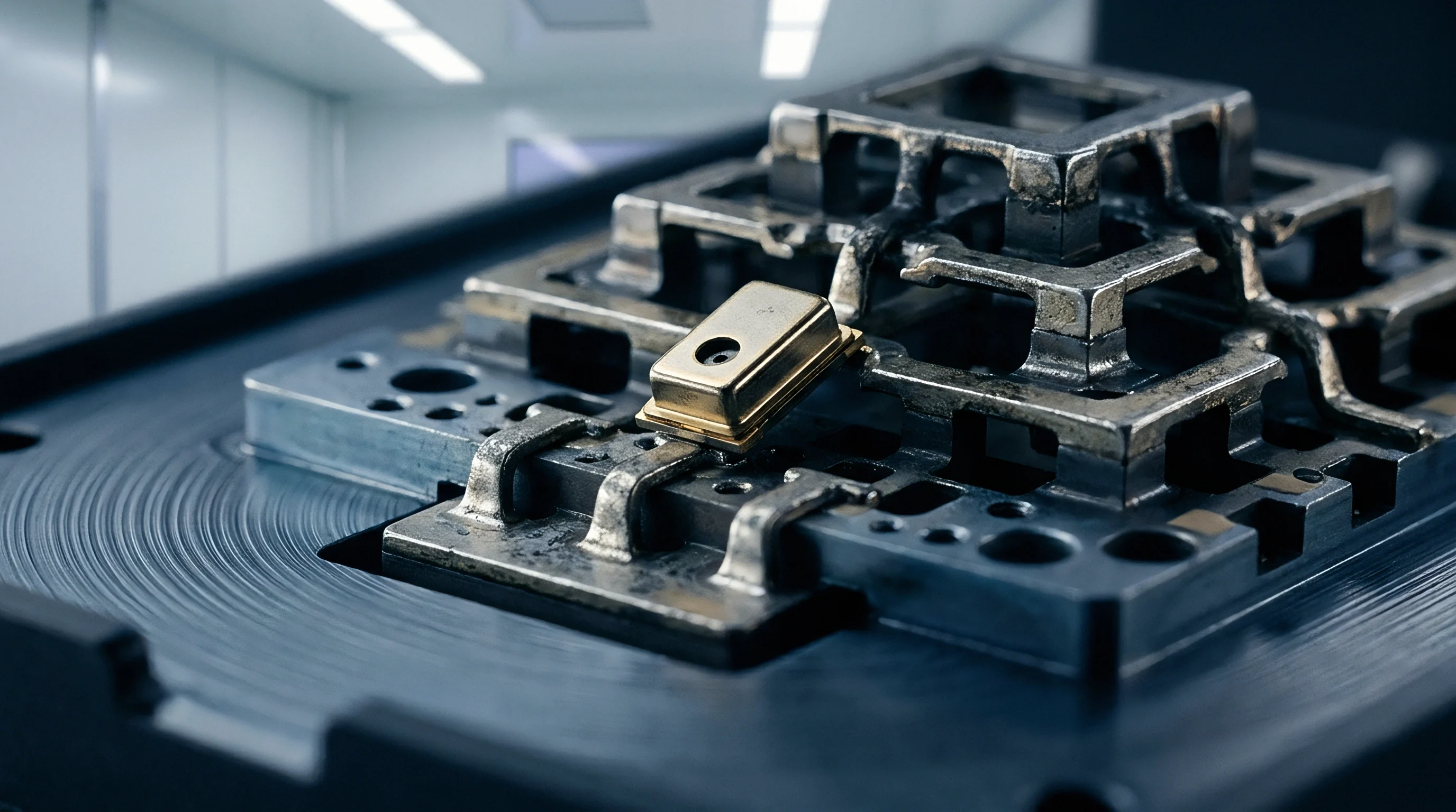
Operating environment ultimately determines whether aging stays on the manufacturer’s baseline curves or accelerates sharply. Moisture ingress is the most aggressive driver of field drift. Ceramic packages rely on gold-tin seam welding or glass frit bonding for hermetic sealing, graded against helium gross- and fine-leak rates under MIL-STD-883 Method 1014.
Under standard fine-leak limits, packages permit exchange rates up to 1 x 10^-9 standard cubic centimeters of helium per second.
Over years in humid tropical environments, water vapor diffuses past that seal boundary even in parts meeting commercial leak specs. Once inside the cavity, moisture condenses on the electrode surfaces, forming hydroxyl bonds and driving galvanic mass transfer. In agricultural soil sensors or container trackers subjected to 85 percent relative humidity at 60 degrees Celsius, mass loading can accelerate aging by a factor of ten compared to benign indoor conditions.
Atmospheric Ingress and Thermal Cycling Regimes
Thermal cycling in industrial settings slowly fatigues the package seal seams. Deployments in deserts or manufacturing plants often see daily temperature swings of 40 to 60 degrees Celsius. Repeated expansion cycles work at the solder bead around the lid until micro-cracks form.
Once hermeticity breaks down, oxygen, moisture, and ambient contaminants enter the cavity, causing rapid and permanent frequency drift.
Industrial atmospheres containing hydrogen sulfide, sulfur dioxide, or chlorine attack compromised packages aggressively. Sulfur reacts directly with exposed silver or finds paths through imperfect nickel plating, growing silver sulfide (Ag₂S) whiskers and adding heavy mass loading. This corrosion raises equivalent series resistance and erodes the oscillator’s negative resistance margin.
If that margin drops below three to five times the crystal’s equivalent resistance, the oscillator simply fails to start, permanently disabling the node.
- Verify hermetic seal integrity using combined fluorocarbon bubble testing and krypton-85 isotopic fine leak detection down to 10^-10 mbar·l/s.
- Implement conformal coating barrier materials on assembled circuit boards to minimize direct atmospheric exposure around crystal package edges.
- Select seam-welded gold-tin enclosures instead of glass-frit sealed ceramic packages for field deployments exposed to continuous thermal vibration.
- Enforce crystal drive level limits below twenty microwatts within radio transceiver registers to eliminate acoustic boundary stress.
Reflow profiles impose an early thermal shock of their own. On double-sided assemblies, crystals on the primary side undergo a second reflow pass that can degrade internal organic getters, releasing captured hydrocarbons onto the fresh electrodes. Limiting time above liquidus during assembly prevents this early loss of factory calibration.
Rigorous incoming lot qualification ensures baseline frequency drift stays within design limits before hardware ever reaches harsh field environments.