Low Frequency Correlation between Small Chambers and Test Sites
Low-frequency chamber pre-scans require mathematical transfer functions to correct for standing waves and height-scan limits before formal site testing.


Resonance
A radiated emission measurement at 43 MHz in a compact semi-anechoic room can show an artificial 8 dB margin under the CISPR 32 Class B limit, only to fail by 4 dB during formal qualification on a 10-meter open site. The issue comes down to enclosure physics. At 30 MHz, free-space wavelength is 10 meters, which calls for deep absorber bulk to match wave impedance.
But hybrid pyramidal cones in a compact 3-meter chamber rarely exceed 0.6 to 0.75 meters, so energy bouncing off the steel walls between 30 MHz and 100 MHz sets up standing waves right across the working volume.
Absorption falls off quickly below one hundred megahertz. At those wavelengths, the face of a short absorber cone cannot provide a gradual impedance taper; incoming energy punches through the foam, bounces off the steel shield behind it, and returns to the quiet zone out of phase. Depending on where the Device Under Test (EUT) sits relative to the receive antenna, this reflected energy sums with or cancels the direct ray, manufacturing false peaks or carving out artificial nulls that hide genuine non-compliance.

Standing Waves below Two Hundred Megahertz
Room dimensions fix the modal distribution. A chamber measuring 7 meters long, 3 meters wide, and 3 meters high develops fundamental resonances starting between 20 MHz and 50 MHz. The resulting standing waves set up spatial nodes where field intensity drops near zero, alongside anti-nodes that sharply amplify field strength.
Sintered ferrite tiles give usable plane-wave absorption down to 30 MHz at normal incidence, but performance degrades quickly at oblique angles. When an EUT radiates toward chamber corners or along wall-floor seams, the effective permeability of the tiles drops, creating localized reflection hot spots that distort the baseline site attenuation. Rather than remaining steady across the band, the measurement error swings sharply as frequency steps upward through the lower spectrum.
Standard 0.6-meter hybrid absorber cone depth yields less than 4 dB reflection loss at 30 MHz inside a 7-meter chamber.
Pre-compliance scans in uncalibrated compact rooms often overlook modal distribution entirely. Engineering teams will chase a 60 MHz harmonic trace with board-level decoupling changes when the observed spike is purely an enclosure artifact. At the same time, real emissions sitting at nodal frequencies sail through unflagged, only to show up full strength the moment the product lands on an open-area qualification site.

Absorber Depth Constraints in Compact Cavities
Enclosure boundaries limit absorber depth. Dedicating 1.5 meters of wall treatment to choke off reflections at 30 MHz shrinks usable floor space past practical limits: an enclosure built with outer dimensions of 7 by 4 meters loses 3 meters of internal length and width once deep carbon-loaded foam pyramids line opposing walls.
Truncated absorbers are an economic compromise. Hybrid treatments back short, lossy foam pyramids with thin ferrite tiles to preserve working volume. While this stabilizes performance from 200 MHz to 18 GHz, attenuation between 30 MHz and 100 MHz rests almost entirely on the ferrite substrate.
Reflection coefficients for ferrite installations below 80 MHz hover between -6 dB and -10 dB, allowing up to 25 percent of incident energy to bounce back into the quiet zone. As that residual energy mixes with direct radiation, measured field strength diverges sharply from ideal ground-plane behavior, producing false passes, surprise test failures, and unplanned redesigns.

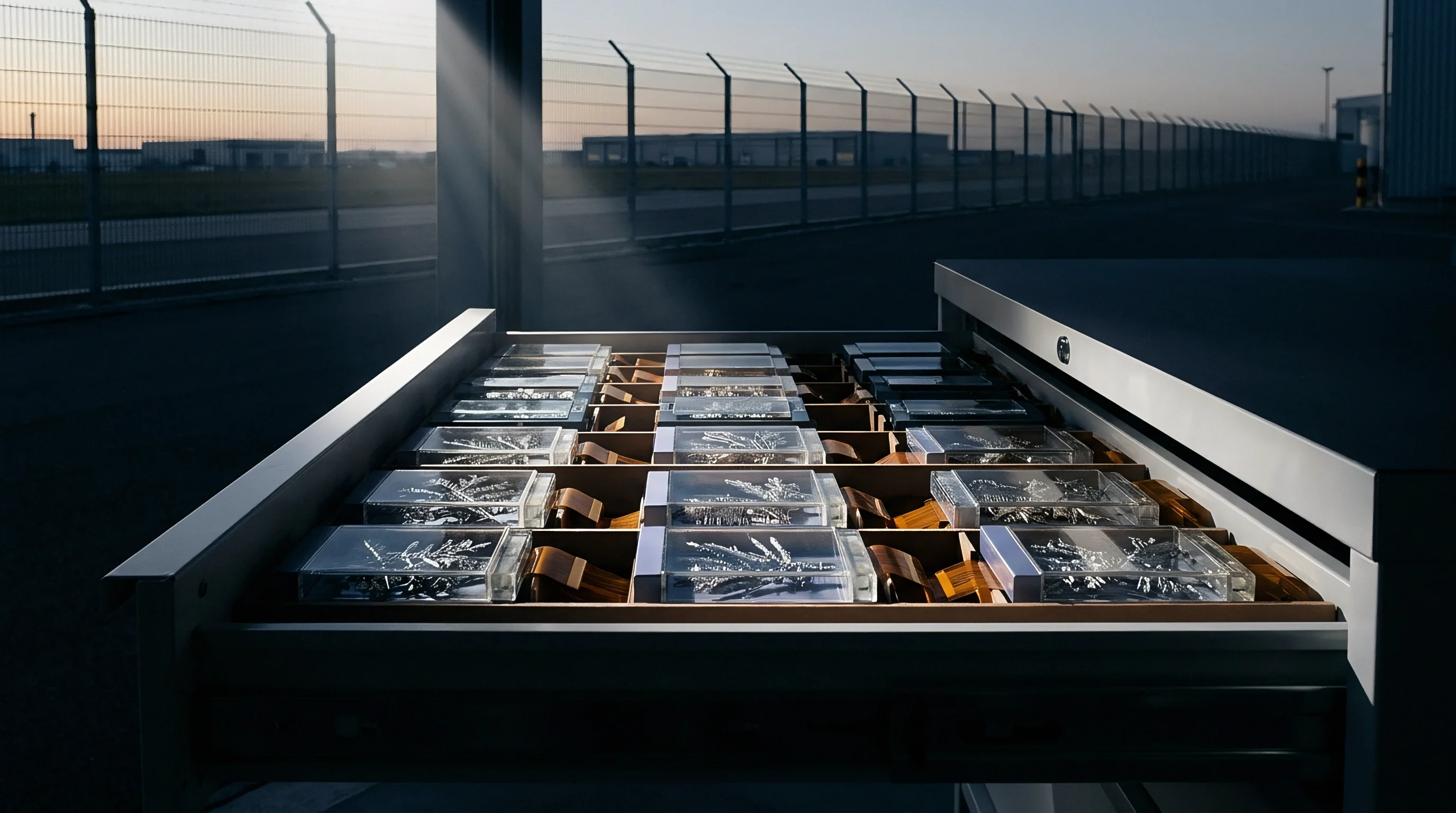
Mast
Scanning a receive antenna from 1 meter to 4 meters above a conducting ground plane is standard practice in accredited 3-meter and 10-meter semi-anechoic measurements under ANSI C63.4 and CISPR 16-1-4. The vertical sweep is necessary to catch constructive interference peaks between the direct wave and ground bounces. Compact rooms with low ceilings compress that travel, frequently capping the mast between 1 meter and 1.5 meters, which misses emission lobes that form higher up at low frequencies.
At 30 MHz, the path-length difference between line-of-sight radiation and the ground reflection demands substantial mast travel to trace out the interference envelope. If ceiling height truncates the scan, the receiver captures an incomplete slice of space. Should the lobe peak at 2.8 meters at a particular turntable azimuth, a mast restricted to 1.5 meters will read up to 6 dB below actual field strength.

Ground Reflection Geometry and Scanning Truncation
Ground reflection mechanics differ fundamentally between Fully Anechoic Rooms (FARs) and Semi-Anechoic Chambers (SACs). Semi-anechoic testing uses a metallic floor and relies on mast height scanning to find maximum field intensity. Fully anechoic rooms line the floor with absorbers to approximate free space.
Converting free-space field strength to ground-plane equivalents assumes an ideal 6 dB difference, but residual reflections off floor absorbers in small FARs inject uneven phase errors across the lower frequencies, breaking the mathematical link between FAR and SAC readings.
Tabletop equipment radiates complex patterns below 100 MHz. AC power leads, I/O cables, and protective grounds behave like unintentional dipoles whose main lobes steer through three dimensions as the turntable rotates. Restricting mast elevation misses these tilted lobes, producing sharp divergences between internal pre-scans and formal 10-meter qualification results.

Antenna Phase Center Shifts at Low Frequencies
Broadband antennas do not maintain a stationary electrical center. Across biconicals, log-periodic dipole arrays (LPDAs), and hybrid BiLog antennas, the phase center drifts along the boom as frequency changes. At 30 MHz, a hybrid antenna’s phase center settles near the back elements, lengthening the actual separation distance well past the nominal 3-meter line calibrated at the element tips.
That extra distance introduces systematic measurement error. In a chamber with a nominal 3-meter tip-to-tip spacing, a 0.4 meters drift toward the rear pushes the true distance to 3.4 meters. By the inverse-distance law, this discrepancy pulls measured amplitude down by roughly 1.1 dB.
Combined with localized phase errors from ground reflections, phase center drift compromises low-frequency calibration factors.
| Facility Type | Nominal Distance | Height Scan Range | Ground Floor Setup | Typical Low-Freq Uncertainty | Regulatory Status |
|---|---|---|---|---|---|
| Open Area Test Site (OATS) | 10 meters | 1.0 m to 4.0 m | Solid Conductive Plane | +/- 3.2 dB | Full Acceptance (Gold Standard) |
| Full SAC (10-Meter) | 10 meters | 1.0 m to 4.0 m | Solid Conductive Plane | +/- 3.6 dB | Full Acceptance (Global standard) |
| Compact SAC (3-Meter) | 3 meters | 1.0 m to 1.5 m | Solid Conductive Plane | +/- 5.8 dB | Restricted Acceptance (Requires NSA check) |
| Fully Anechoic Room (FAR) | 3 meters | Fixed (1.5 m) | Absorber-Covered Floor | +/- 5.2 dB | Allowed for specific standards (e.g. CISPR 32) |
| GTEM Cell (Large) | 1 to 1.5 meters | N/A (Fixed septum) | Enclosed Structure | +/- 7.0 dB | Pre-compliance / Screening only |
Compact dimensions place strict demands on antenna selection. Setting up large biconicals in a tight chamber brings the elements into the near-field zone of wall absorbers. Mutual coupling between elements and absorbing material shifts antenna drive impedance, voiding standard factory calibration factors.
Unless routines correct for wall proximity, the resulting data carries systematic amplitude bias.
Truncated height scans and near-field boundary coupling make uncorrected small-chamber measurements useful primarily for relative diagnostics rather than pass-fail compliance determinations.


Correction
Converting small-chamber spectral scans into dependable predictions of 10-meter open-site performance requires a structured transfer matrix instead of a flat numerical offset. Relying on a fixed +10.5 dB scaling factor to translate 3-meter data to 10-meter levels fails below 100 MHz, where near-field components govern propagation and boundary reflections corrupt the field.
A working correction routine applies localized profiles based on Normalized Site Attenuation (NSA) deviations measured during chamber qualification under ANSI C63.4-2014 or CISPR 16-1-4. Subtracting measured chamber NSA error from raw spectrum traces recovers baseline alignment with free space, even if near-field coupling errors remain.
What Triggers Rejection under Radiated Emission Rules?
Regulatory authorities reject filings whenever measurement uncertainty exceeds limits set by governing standards or validation records fall short. Submitting an application backed by data from a compact facility where site attenuation strays more than +/-4 dB from theoretical NSA benchmarks prompts immediate suspension by Telecommunication Certification Bodies (TCBs) or Notified Bodies.
Examining a worked conversion for a low-frequency emission demonstrates how correlation gaps develop.
Take an electronic host generating a narrowband spurious emission at 45 MHz, measured in a 3-meter compact fully anechoic room (FAR) with the antenna held at 1.5 meters. The spectrum analyzer reads 34.0 dBuV/m through a calibrated broadband antenna. The target standard is CISPR 32 Class B radiated emissions, evaluated at 10 meters in a semi-anechoic environment, where the limit is 30.0 dBuV/m.
The conversion proceeds through four steps:
- FAR-to-SAC Floor Reflection Addition ~ Converting from a fully anechoic environment (free-space approximation) to a semi-anechoic environment (ground plane reflection) requires adding the theoretical maximum ground bounce reflection vector. Assuming complete constructive phase addition, add +6.0 dB. Calculated field strength: 34.0 + 6.0 = 40.0 dBuV/m at 3 meters.
- Distance Scaling Factor ~ Scaling field strength from 3 meters to 10 meters under standard 20 dB per decade inverse-distance law requires subtracting 20 log10(10 / 3) = 10.46 dB. Calculated field strength: 40.0 – 10.46 = 29.54 dBuV/m at 10 meters.
- Low-Frequency Near-Field Distance Correction Adjustment ~ At 45 MHz, wavelength equals 6.67 meters. A 3-meter measurement distance resides within the near-to-far-field transition region (2 wavelength / 2-pi = 2.12 meters). The simple 20 dB/decade distance attenuation overstates signal decay. The empirical near-field correction adjustment adds +2.8 dB back to the calculated level. Calculated field strength: 29.54 + 2.8 = 32.34 dBuV/m at 10 meters.
- Chamber Site Attenuation Residual Variance Correction ~ Chamber calibration records show the compact FAR exhibits a site attenuation deviation (NSA defect) of -3.5 dB at 45 MHz due to absorber reflection limitations. Applying the site calibration offset (+3.5 dB) yields the final predicted 10-meter site field strength: 32.34 + 3.5 = 35.84 dBuV/m at 10 meters.
The raw 3-meter FAR reading of 34.0 dBuV/m suggested a comfortable 6.0 dB margin against the 3-meter limit of 40.0 dBuV/m. Once adjusted for distance scaling, near-field geometry, and chamber site attenuation defects, the predicted 10-meter field strength reaches 35.84 dBuV/m. That sits 5.84 dB over the 30.0 dBuV/m Class B limit, ensuring a failure during formal qualification.
Several physical mechanisms explain why low-frequency measurements diverge between compact rooms and full-scale regulatory sites:
- Uncalibrated Absorber Saturation ~ Carbon-loaded foam absorbers experience reduced effective dielectric loss under high power or low-frequency magnetic field conditions, causing unexpected reflection variations.
- Ground Plane Edge Diffraction ~ Compact ground planes with truncated metallic boundaries diffract low-frequency waves, creating secondary signal paths toward the receiving antenna.
- Cable Bundle Positioning Discrepancies ~ Small setup tables force interconnecting cables into tight loops, changing common-mode RF current radiation characteristics relative to standard 1-meter straight cable arrangements.
- Turntable Metallic Reflection Coupling ~ Small metal turntables interact inductively with low-hanging EUT wiring, shifting signal resonant frequencies down into the 30 MHz to 60 MHz region.
ANSI C63.4 Clause 5.4 mandates normalized site attenuation within +/-4 dB of theoretical values before any 3m compact site data can support an FCC Part 15 grant filing.
Relying on raw small-chamber traces without mathematical compensation matrix offsets leads directly to late-stage engineering redesigns.
Engineering teams frequently assume that because a device cleared limits inside an internal screening box, the accredited test lab must be using flawed antenna factors.


Grant
Securing radio equipment authorizations requires accredited test reports across jurisdictions, including FCC Part 15 (US), EU Radio Equipment Directive 2014/53/EU (CE mark), Innovation, Science and Economic Development RSS-247 (Canada), Radio Law / Giteki (Japan), KC Certification (South Korea), and SRRC (China). Regulators require test data from facilities accredited to ISO/IEC 17025. Data from unaccredited internal chambers cannot appear in technical dossiers submitted for formal grant issuance.
A modular grant stops at the host interface. Dropping a pre-certified radio module into a host design does not relieve the manufacturer from evaluating radiated spurious emissions. Digital processing, power management ICs, and high-speed buses on the host board routinely generate unintentional emissions between 30 MHz and 300 MHz.
If host integration alters the radiated spurious profile, permissive change regulations apply.

Modular Limits across Regulatory Filing Routes
Modular approvals set rigid operational boundaries. Enclosure materials and internal harness layouts must follow the original integration instructions. Swapping an aluminum housing for plastic or rerouting flexible printed circuit (FPC) cables changes shielding effectiveness at low frequencies.
Under FCC rules, changes to host shielding or antenna layout require assessment under Class I or Class II Permissive Change (C2PC) frameworks. A Class II Permissive Change requires formal radiated spurious data from an accredited 3-meter or 10-meter chamber submitted to a TCB. Attempting to support integration updates with unaccredited pre-compliance scans risks non-compliance notices, stop-ship directives, or customs holds.
Permissive Change Thresholds for Radiated Spurious
Standard regulatory frameworks impose clear compliance thresholds for permissive change evaluation across global markets:
- FCC Class I Permissive Change (C1PC) ~ Applies to design modifications that do not degrade radiated spurious levels. Internal screening data may guide risk assessment, but documentation must remain on file.
- FCC Class II Permissive Change (C2PC) ~ Required when design changes increase radiated emissions while remaining within legal limits. Demands formal accredited test lab reports; pre-compliance data is strictly inadmissible.
- EU RED Risk Assessment ~ Demands updating the technical file under EN 301 489-1 and EN 55032. The manufacturer assumes full legal liability for Declaration of Conformity (DoC) accuracy.
- South Korea KC Permissive Modificaton ~ Requires submitting hardware modification dossiers to designated research agencies, with re-testing enforced for changes affecting EMC properties.
Evaluating internal pre-compliance scan data requires following a clear operational protocol before booking formal laboratory campaigns:
- Verify that internal compact chamber site attenuation calibration data has been updated within the preceding twelve months.
- Apply near-field to far-field correction matrices and frequency-dependent absorber loss offsets to all raw 3-meter trace data.
- Compare corrected emission peaks against target regulatory limits, maintaining a minimum required engineering margin of 6 dB to account for laboratory measurement uncertainty.
- Inspect cable harness layouts to ensure physical arrangement mirrors formal CISPR 32 tabletop configuration requirements.
- Identify any low-frequency spurious signal that falls within 3 dB of the limit line and schedule targeted pre-qualification scans in an accredited 10-meter facility.
Low frequency emissions that vanish when an antenna turns horizontal usually originate from long external cabling rather than printed circuit board traces.
Compliance documentation must state the exact physical facility configuration used during qualification testing.
Commercial supply contracts typically stipulate that the supplier warrants that all radio integration files conform to host-level radiated emission limits as defined by ISO/IEC 17025 accredited laboratory reports submitted prior to commercial distribution.
Variance
Disagreements between accredited laboratories testing the same hardware typically boil down to cable geometry and setup details between 30 MHz and 100 MHz. Measurement uncertainty calculations under CISPR 16-4-2 permit up to +/-5.2 dB of margin below 1 GHz. An EUT reading 38 dBuV/m at Laboratory A can easily register 43 dBuV/m at Laboratory B due to table construction differences, cable height above the reference plane, or slight divergence in antenna calibration curves.
Cable dressing on tabletop setups is especially sensitive. CISPR 32 requires bundling excess interface cables near the center in a 30 to 40 cm z-fold. Letting an I/O lead dangle off the edge of the turntable allows capacitive coupling to the floor absorbers or the conductive ground plane.
That alters the effective aperture of the cable run and can swing measured levels by up to 8 dB at low frequencies.

Cable Harness Layout Impact below One Hundred Megahertz
Unshielded power cables readily turn into radiators. Switch-mode AC/DC adapters produce high-frequency switching noise, driving common-mode currents down DC supply leads into the host unit. Below 100 MHz, a typical 1.5 meters power lead approaches quarter-wavelength resonance near 50 MHz.
Shifting cable orientation alters the radiated field as the turntable turns. Raising an unshielded power lead just 10 cm above the tabletop changes the characteristic impedance of the transmission line it forms with the ground plane, producing notable differences between successive runs.
| Setup Parameter | Standard CISPR 32 Requirement | Common Pre-Scan Deviation | Observed Amplitude Variance | Primary Physical Driver |
|---|---|---|---|---|
| Cable Z-Bundling | 30 cm to 40 cm neat z-fold | Loose loop or unbundled drape | 3.0 dB to 7.5 dB | Common-mode loop area shift |
| EUT Height Above Plane | 80 cm (tabletop) | 70 cm to 85 cm non-standard table | 2.0 dB to 4.5 dB | Capacitive floor coupling variation |
| Power Lead Separation | 10 cm clear of other cables | Bundled parallel with data lines | 4.0 dB to 9.0 dB | Crosstalk and parasitic RF injection |
| Turntable Material | Low-permittivity wood/plastic | Metal sub-frame or dense wood | 2.5 dB to 6.0 dB | Inductive coupling to EUT base |
| AC Mains Filter Setup | Flush under ground plane | Exposed cable run on floor | 5.0 dB to 11.0 dB | Direct cable-to-antenna radiation |

Laboratory Measurement Uncertainty and Regulatory Margins
Filing for product certification requires factoring in combined measurement uncertainty. TCB reviewers and market surveillance bodies like Bundesnetzagentur in Germany or Ofcom in the UK routinely pull retail units for audit testing in state facilities. If a filing relies on an accredited report showing only a 0.5 dB margin, inter-laboratory variance alone can turn that passing result into an audit failure.
A formal ISO/IEC 17025 compliant test report must document complete environmental and setup records for low-frequency validation:
- Complete schematic map detailing cable routing, z-fold dimensions, and height above the ground plane.
- Specific model, series number, and calibration expiration dates for all biconical and BiLog measurement antennas.
- Normalized site attenuation correction table applied to the raw spectrum data.
- Uncertainty budget calculation sheet compiled according to CISPR 16-4-2 mandates.
- Firmware build number, operating state code, and system clock speeds forced during scanning.
Unaccredited scans carry no formal standing with regulatory agencies.
An engineering chamber pre-scan without standardized cable bundling records artificial compliance that disappears in an accredited test facility.
Developing transfer functions for non-standard compact rooms requires balancing calibration rigor against the high cost of booking reference time in a 10-meter SAC.

Outlay
Chamber queues back up during peak product release cycles. Booking time at an accredited 10-meter semi-anechoic facility runs between $250 and $450 per hour, with full qualification runs for multi-radio wireless hosts taking 40 to 80 laboratory hours. Failing radiated emissions during that campaign adds between $10,000 and $35,000 in direct lab fees, before factoring in engineering hours.
A retest cycle easily adds four weeks to a launch schedule. On a product targeting $2,000,000 in first-year sales, a four-week delay translates to roughly $150,000 in displaced top-line revenue ~ far exceeding the cost of proper pre-compliance screening.

Quantifying Pre-Scan Chamber Economics against Retest Risk
An internal screening setup balances capital investment against the risk of qualification failures. Setting up a 3-meter compact FAR or a large GTEM system requires an initial capital outlay of $80,000 to $200,000. To prevent misleading passes, that investment has to be paired with transfer matrices that compensate for cavity geometry.
Comparing raw pre-scanning, mathematically compensated pre-screening, and unvetted laboratory qualification illustrates the financial tradeoffs:
| Strategy Approach | Initial Pre-Scan Outlay | Accredited Lab Hours | Retest Probability | Average Schedule Slip | Total Financial Risk Exposure |
|---|---|---|---|---|---|
| Direct Qualification (No Pre-Scan) | $0 | 60 to 90 hours ($22,500) | 45 percent | 4 to 6 weeks | $35,000 to $85,000 |
| Uncorrected Small-Chamber Pre-Scan | $15,000 (Internal) | 50 to 70 hours ($17,500) | 35 percent | 3 to 5 weeks | $28,000 to $65,000 |
| Corrected Matrix Small-Chamber Pre-Scan | $25,000 (Internal + Cal) | 40 to 50 hours ($12,500) | 8 percent | 0 to 1 week | $5,000 to $15,000 |
| Full 10m SAC Pre-Qualification Scan | $12,000 (External Lab) | 40 to 50 hours ($12,500) | 2 percent | 0 weeks | $2,000 to $5,000 |

Global Approval Sequencing and Landed Cost Controls
Coordinating global approvals (FCC, CE, SRRC, Giteki, KC) requires an aligned test plan to avoid paying for redundant lab time. Because European EN 301 489-1 and US FCC Part 15 subpart B specify comparable low-frequency limits, pulling a single, high-margin dataset from a 10-meter SAC allows host integrators to populate multiple regional technical files at once.
Proper filing sequence prevents secondary compliance costs from compounding. Securing an FCC grant backed by robust 10-meter chamber data expedites approvals in regions that accept FCC test dossiers with minimal administrative addenda. Conversely, leaning on uncompensated small-chamber pre-scans creates conflicting data, invites agency audits, hangs up customs clearance, and leaves inventory stranded on the dock.