Meaning
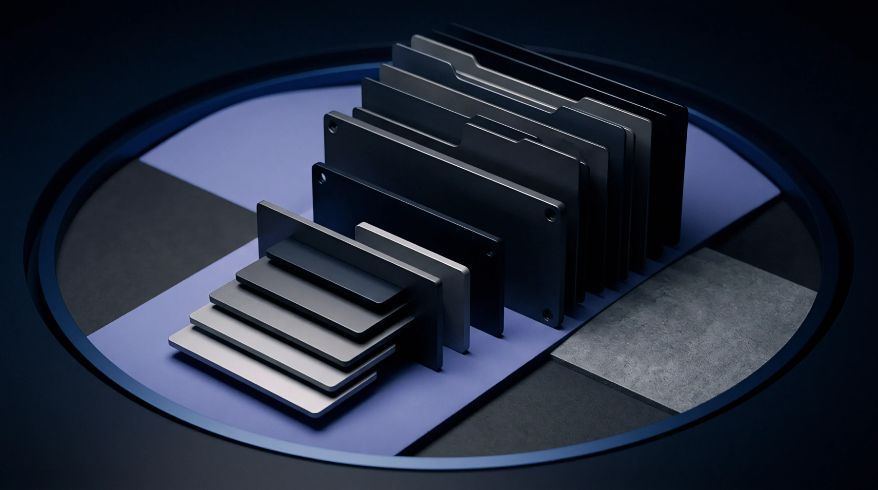
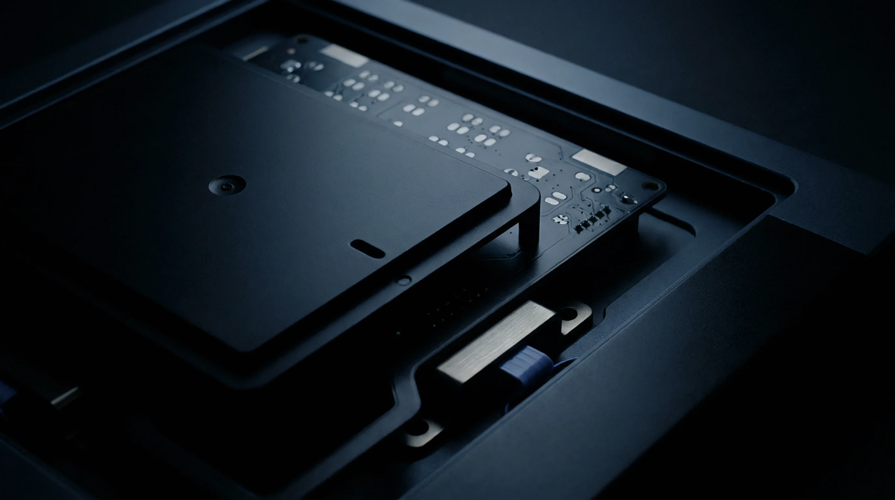
An array of spring-loaded pins organized on a contact plate creates a bed of nails test jig to enable electrical verification of assembled printed circuit boards. This mechanical fixture interfaces with predesignated test points on the solder side of a board during production to detect short circuits, open paths, or incorrect component values before final power application. A board undergoes contact via a vacuum or pneumatic press mechanism that drives the pins into the conductive pads.
The hardware establishes a connection between the unit under test and an automated diagnostic controller. Verification stops at the physical interconnect layer where the pins verify individual trace integrity rather than complex software functional performance.
Fixture Alignment
Precision guide pins ensure the correct registration of the board over the pin matrix to prevent damage during the compression phase. Each pin probe possesses a specific tip geometry selected for the contact surface finish or pad shape. If a board shifts by a fraction of a millimetre, the spring force concentrates on the edge of a component or a trace instead of the intended test pad.
This misalignment risks permanent deformation of the copper surface or fractures in the underlying substrate. Alignment tolerances depend on the density of the probe pattern and the pitch of the components nearby. Maintaining a consistent vertical approach path allows the compression force to distribute across the entire surface area of the fixture.
Mechanical stability during the stroke cycle dictates the accuracy of the probe contact.
Probe Contact
Consistent electrical contact relies on the spring constant of individual probes and the travel distance of the plunger. A test jig employs probes with varying head styles to accommodate different pad morphologies or through hole vias. The force required to penetrate oxidation on the pad surface must remain within the limits defined by the board manufacturer to prevent pad lifting or laminate stress.
Excessive pressure bends the pins or damages the test point, while insufficient pressure causes intermittent connection faults that produce false failures. The probe tip interacts with the target using a controlled downward movement until the spring compresses to the specified length. Electrical resistance between the probe and the pad stays below the threshold defined by the automated tester.
Each probe wears down over thousands of contact cycles, requiring periodic replacement based on the internal count of test pulses.
System Integration
Final product verification occurs when the board exits the assembly line and meets the fixture on the factory floor. The tester validates connectivity against the netlist extracted from the original design file to confirm that each connection matches the intended routing scheme. This verification step separates bare board manufacturing defects from assembly errors like solder bridges or reversed passive parts.
A diagnostic failure highlights the exact net or component identifier for repair technicians. Corrective action proceeds through rework of the identified area before the board returns to the inspection queue. This hardware configuration provides the final gate for electrical quality in high volume electronic production.