Meaning
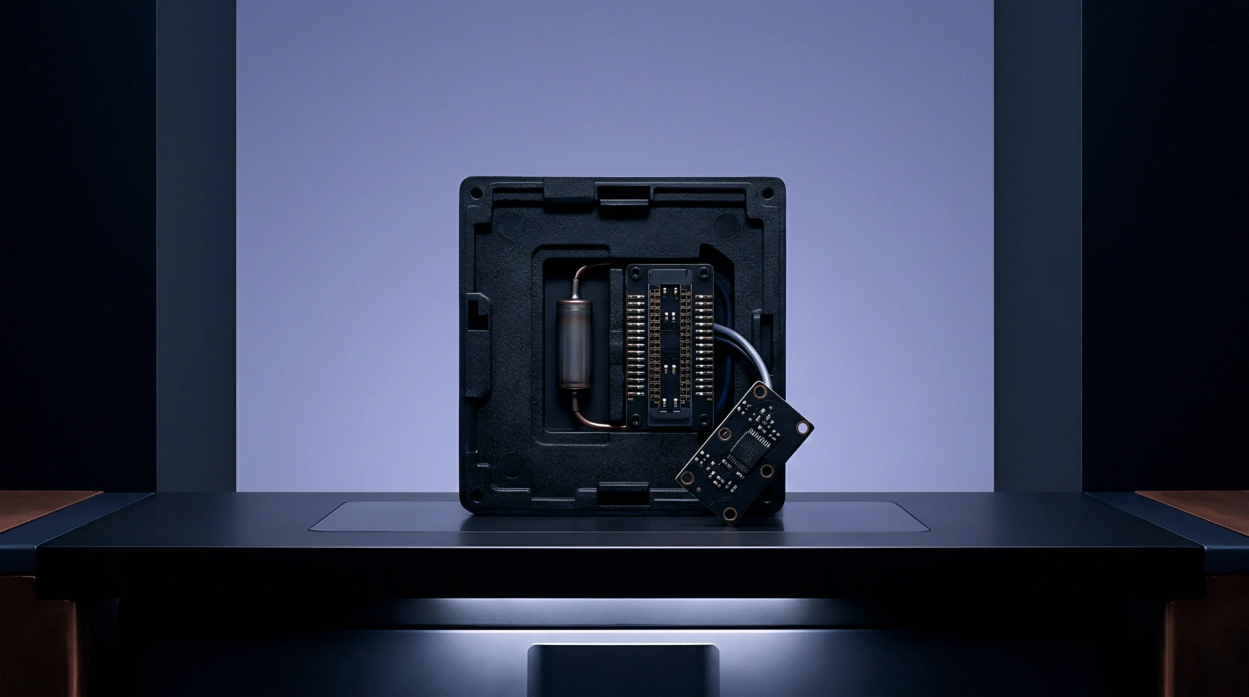
Metallic enclosures soldered directly to printed circuit board surfaces suppress electromagnetic interference across high frequency transceiver circuits. A board level shield confines radiated emissions from sensitive clock generators while blocking external noise sources from coupling into adjacent low noise amplifiers. Mechanical retention relies on either a two piece assembly featuring a soldered frame with a removable snap on cover or a one piece stamped fence soldered straight to the ground traces.
Thermal management considerations dictate aperture placement across the upper surface to allow convective airflow without compromising attenuation performance at target frequencies.
Interference Attenuation
Electromagnetic leakage suppression depends upon maintaining continuous electrical contact around the perimeter trace network without gaps exceeding one tenth of the wavelength at the highest operating frequency. Eddy currents generated within the conductive lid create opposing magnetic fields that cancel out internal noise radiation before it reaches neighboring passive components. Higher permeability alloys provide superior low frequency magnetic field absorption, whereas copper based variants maximize electrical conductivity for high frequency electric field reflection.
Galvanic compatibility between the shield material and the underlying circuit board plating prevents electrochemical corrosion during salt spray exposure testing.
Thermal Budget
Enclosure installation alters localized thermal dissipation paths by introducing an additional thermal resistance barrier between enclosed components and ambient enclosure air. Power amplifiers operating inside restricted cavities require thermal interface pads compressed between the component package top and the underside of the removable cover to facilitate conductive heat transfer. Computational fluid dynamics simulations model these internal conduction paths alongside external chassis airflow to verify that junction temperatures remain below specified semiconductor maximum ratings under worst case operating loads.
Material thickness selection balances mechanical rigidity against thermal mass, ensuring rapid solder reflow during surface mount manufacturing without warping the contact edges.
Mechanical Qualification
Vibration testing subjects soldered enclosures to high frequency random profiles that simulate transport and operational conditions in harsh automotive or aerospace environments. Solder joint fatigue failures occur when differential thermal expansion between the stamped metal alloy and the fiberglass substrate places excessive cyclic shear stress on the fillet joints. Destructive cross section analysis confirms adequate solder wetting along the entire perimeter leg length following standard drop tests and thermal shock cycles.
Final factory inspection protocols verify coplanarity across all contact corners to guarantee reliable electrical grounding prior to automated optical placement on the production line.