Evaluating Unresolved Host Level Re-Testing Protocols for Multi-Transmitter Industrial Embedded Devices
Host level re-testing for multi-transmitter industrial embedded devices requires evaluating simultaneous transmission intermodulation products inside a semi-anechoic chamber whenever antenna separation drops below 20 cm.


Topology
Placing multiple radio modules inside a single industrial housing completely changes the RF environment for every transmitter on board. Pre-certified modules are tested in isolation, usually on standardized reference boards suspended in free space. Mounting those same radios onto a shared host PCB within a die-cast aluminum or heavy polycarbonate enclosure invalidates those individual test reports.
Near-field coupling between adjacent trace antennas, parasitic capacitance between heat sinks and RF paths, and shared ground return routes give rise to unintended radiation mechanisms. Modern gateways routinely pack Wi-Fi 6E, Bluetooth LE 5.4, Sub-1 GHz Wi-SUN, and LTE-M or 5G RedCap radios into volumes under 500 cubic centimeters. In such tight layouts, mutual coupling detunes PCB trace antennas, shifts resonant frequencies, and distorts radiation patterns far beyond what modular test scans originally recorded.
Inside small host enclosures, antenna spacing often drops below the 20-centimeter threshold that regulatory bodies require for independent assessment. Below this boundary, electromagnetic fields interact directly in the reactive near-field zone. Electric and magnetic field vectors from a cellular module transmitting at 23 dBm induce RF currents into the adjacent traces of a Bluetooth LE transceiver running at 4 dBm.
That induced current modulates non-linear active elements in the Bluetooth front end, generating intermodulation distortion before the signal even leaves the board. Shared power rails make crosstalk worse when fast voltage regulator switching transients leak RF ripple across common power planes.

Transmitter Densities in Industrial Hardware
Modern programmable logic controllers and remote terminal units routinely pair high-throughput short-range radios with long-range cellular backhaul. System operational demands usually require concurrent transmission, forcing all installed radios to broadcast at the same time to maintain live sensor polling while pushing telemetry to remote enterprise servers. A typical host board might integrate a 2.4 GHz / 5 GHz / 6 GHz Wi-Fi module, a 915 MHz Sub-1 GHz mesh transceiver, and a multi-band cellular engine inside an enclosure measuring 120 millimeters by 80 millimeters by 45 millimeters.
Cramped spatial constraints leave little room for clean antenna layout. Microstrip patch antennas and printed inverted-F antennas along PCB edges often sit just millimeters from metallic walls or internal shielding cans. Conductive boundaries this close create parasitic capacitance that detunes matching networks ~ an antenna matched to 50 ohms in free space can drop to 20 ohms inside the host.
That impedance mismatch reflects power back into the transmitter’s power amplifier, pushing it into non-linear operation and raising harmonic emissions. The table below outlines common multi-transmitter architectural combinations, their typical separation distances, and the dominant coupling mechanisms observed inside industrial host housings.
Module interaction goes deeper than free space ~ it extends straight into the ground plane. High-speed digital signals from host processors and Ethernet PHYs inject broadband noise into the shared PCB ground layer that transceivers reference for RF return currents. If ground return currents from a high-power cellular transmitter flow across ground plane splits or narrow necked ground pours near a sensitive Sub-1 GHz module, local ground potential fluctuates at the cellular carrier frequency.
The ground plane then becomes a secondary radiator, casting off spurious signals that completely bypass individual module shielding.
Industrial host housings constructed from die-cast aluminum alter the near-field antenna pattern of modular transmitters, invalidating individual module approvals that assumed free-space radiation.

Electromagnetic Near-Field Coupling Mechanisms
Reactive near-field coupling dominates whenever antennas sit closer together than one-sixth of the operational wavelength. At 915 MHz, the reactive near-field boundary extends roughly 52 millimeters from the antenna structure; for a 2.4 GHz transceiver, that boundary sits at 20 millimeters. Operating a 915 MHz antenna within 30 millimeters of a 2.4 GHz antenna causes their reactive fields to overlap continuously.
This overlapping alters spatial current distribution across both structures, degrading directional gain and generating unmodeled coupling loss.
Conductive cross-coupling moves through shared voltage regulator circuits and PCB power traces. Industrial host architectures often step down a 24-volt DC main input to a 3.3-volt rail via a primary buck converter, which then feeds dedicated low-dropout linear regulators for each radio module. High RF currents drawn during cellular transmission bursts drop voltage across PCB traces feeding adjacent regulators.
That resulting ripple modulates the power supply rejection ratio limit of the adjacent module’s local oscillator synthesizer, creating sideband phase noise spurs that radiate directly from the secondary antenna.
Chassis cavity resonance introduces another host integration hazard. Metal housings act as resonant cavities at specific RF frequencies dictated by their internal physical dimensions. A rectangular metal enclosure measuring 150 millimeters by 100 millimeters by 50 millimeters internally exhibits its fundamental TE101 cavity resonance near 1.80 GHz.
If a cellular module transmits near 1.80 GHz (such as LTE Band 3 or Band 4 uplink frequencies), the cavity amplifies internal electromagnetic field strength by 15 to 20 dB. The amplified field couples directly into unshielded host traces, memory buses, and adjacent radio modules, causing severe radiated spurious emission compliance failures during host-level testing.

Structural Workflow for Assessing Host Integration Risks
Evaluating multi-transmitter integration risk demands a systematic screening protocol executed before submitting final hardware to an accredited testing laboratory. The following numbered procedure establishes the engineering sequence for assessing co-located radio performance inside an industrial host enclosure.
- Map physical antenna layout geometries across the host PCB assembly, measuring center-to-center spatial separation between all installed modular antennas.
- Measure passive antenna isolation between each antenna port across the operational frequency bands using a calibrated two-port vector network analyzer with the host enclosure fully assembled.
- Perform a conducted spurious emission scan on each individual radio module output port across its full frequency spectrum while adjacent radio modules operate in idle mode.
- Activate simultaneous transmission modes across all co-located wireless modules using automated test firmware scripts that force worst-case duty cycles and maximum output power.
- Conduct an initial radiated pre-scan in a semi-anechoic chamber across 30 MHz to 40 GHz to capture intermodulation spikes and chassis cavity resonances generated under simultaneous broadcast conditions.
Passive isolation measurements direct the scope of necessary host-level re-testing. If measured passive antenna isolation between any two transceivers falls below 20 dB across active operating bands, the risk of active intermodulation spikes increases significantly. Strong RF signals reaching adjacent receiver front-ends or transmitter output stages trigger non-linear mixing products that single-module test reports cannot predict.
Engineering teams must evaluate whether observed spurious signals stem from linear antenna cross-coupling or non-linear mixing within the RF silicon. Linear coupling can often be resolved by improving enclosure shielding or increasing spatial separation. Non-linear mixing requires hardware changes, such as introducing sharp-cutoff bandpass filters between the module output port and the host antenna connector.
Identifying the exact coupling pathway early prevents costly circuit board revisions late in the certification cycle.
The operational state of host processor interfaces plays a critical role during simultaneous transmission evaluation. High-speed memory interfaces, Ethernet controllers, and display drivers generate broadband digital noise that can mix with RF carrier fundamentals inside non-linear host junctions. Exercising the processor, memory, and high-speed buses with thorough diagnostic workloads during radio pre-scans ensures that all combined noise sources surface under simulated operational workloads.
Host integration protocols must also account for temperature-induced frequency drift. Industrial embedded devices often operate across ambient temperatures ranging from -40 degrees Celsius to +85 degrees Celsius. Heat generated by simultaneous high-power cellular and Wi-Fi transmissions raises internal chassis temperatures, altering the center frequency of crystal oscillators and RF filter passbands.
A multi-transmitter system passing spurious emission pre-scans at room temperature can fail at thermal extremes as filter attenuation skirts shift relative to intermodulation product frequencies.
How far must host manufacturers re-evaluate baseline modular compliance when housing materials, internal routing paths, and simultaneous transmission configurations vary across custom industrial product variants?


Shield
Physical containment of spurious radiated fields inside multi-transmitter industrial hardware depends on structural enclosure shielding and PCB-level isolation structures. Metal housings offer high attenuation against radiated electromagnetic fields, yet apertures for status LEDs, cable entry glands, and housing seams reduce effective shielding performance. At higher frequencies, such as the 5.8 GHz and 6 GHz Wi-Fi bands, slot apertures as small as 25 millimeters in length act as resonant slot antennas, allowing internal RF noise to escape into the environment.
Grounding seam integrity across multi-piece metal enclosures requires continuous conductive gaskets or closely spaced ground screws to prevent seam radiation.
Board-level shielding cans placed over individual radio transceivers isolate RF circuitry from internal chassis noise and prevent inter-module cross-talk. Standard tin-plated steel cans deliver 30 to 50 dB of attenuation against radiated near-field coupling up to 3 GHz. Above 3 GHz, aperture slots in the fence walls for clip-on covers begin to leak RF energy.
Solder-down shielding cans with continuous perimeter solder seams provide far better high-frequency attenuation than removable frame-and-cover designs. Ground plane stitch vias around the shield perimeter must maintain spacing tighter than one-twentieth of the highest operating frequency wavelength to block RF leakage through inner PCB layers.

Chassis Resonances and Enclosure Attenuation
Enclosure material selection sets baseline electromagnetic attenuation properties. Die-cast aluminum alloy housings provide over 60 dB of structural shielding against far-field radiated electromagnetic waves across the 30 MHz to 18 GHz spectrum. Polycarbonate and ABS plastic enclosures provide zero intrinsic RF shielding, relying entirely on internal conductive coatings or vacuum-metallized layers.
Thin conductive coatings applied to internal plastic surfaces often crack around mounting posts and seam edges during mechanical assembly, destroying shield continuity and creating localized RF leakage paths.
Chassis seam geometries dictate high-frequency containment capability. Flat butt-joint seams between enclosure halves allow RF energy to radiate along the entire seam length. Lap-joint seams with tongue-and-groove profiles present a non-linear path that reduces RF leakage.
Incorporating conductive silicone gaskets filled with nickel-graphite or silver-aluminum particles along enclosure seams maintains low transfer impedance across housing interfaces. The graph of transfer impedance versus seam fastener compression reveals that inconsistent screw torque leads to localized transfer impedance spikes, causing radiated emission failures at specific harmonic frequencies.
Aperture arrays designed for thermal ventilation act as high-pass waveguide filters. The cutoff frequency of a rectangular aperture depends on its longest diagonal dimension. An aperture with a maximum dimension of 15 millimeters exhibits a waveguide cutoff frequency near 10 GHz.
Signals below this cutoff frequency undergo exponential attenuation as they travel through the aperture depth. However, if the wall thickness of the enclosure is thin (under 1.5 millimeters), the attenuation offered by the aperture depth drops rapidly, enabling strong radiated emission leakage at frequencies well below the theoretical cutoff point.
Internal cable harnesses routed past radio modules disrupt enclosure shielding performance. Unshielded ribbon cables carrying digital display or sensor data act as effective pick-up antennas inside the chassis. High-frequency RF fields radiated by a 2.4 GHz module couple onto the cable conductors, traveling along the wiring harness until reaching external connector interfaces.
Once at the connector interface, the RF energy radiates into free space, bypassing enclosure shielding entirely. Equipping internal data cables with common-mode ferrite cores adjacent to PCB headers suppresses cable-borne RF conduction.
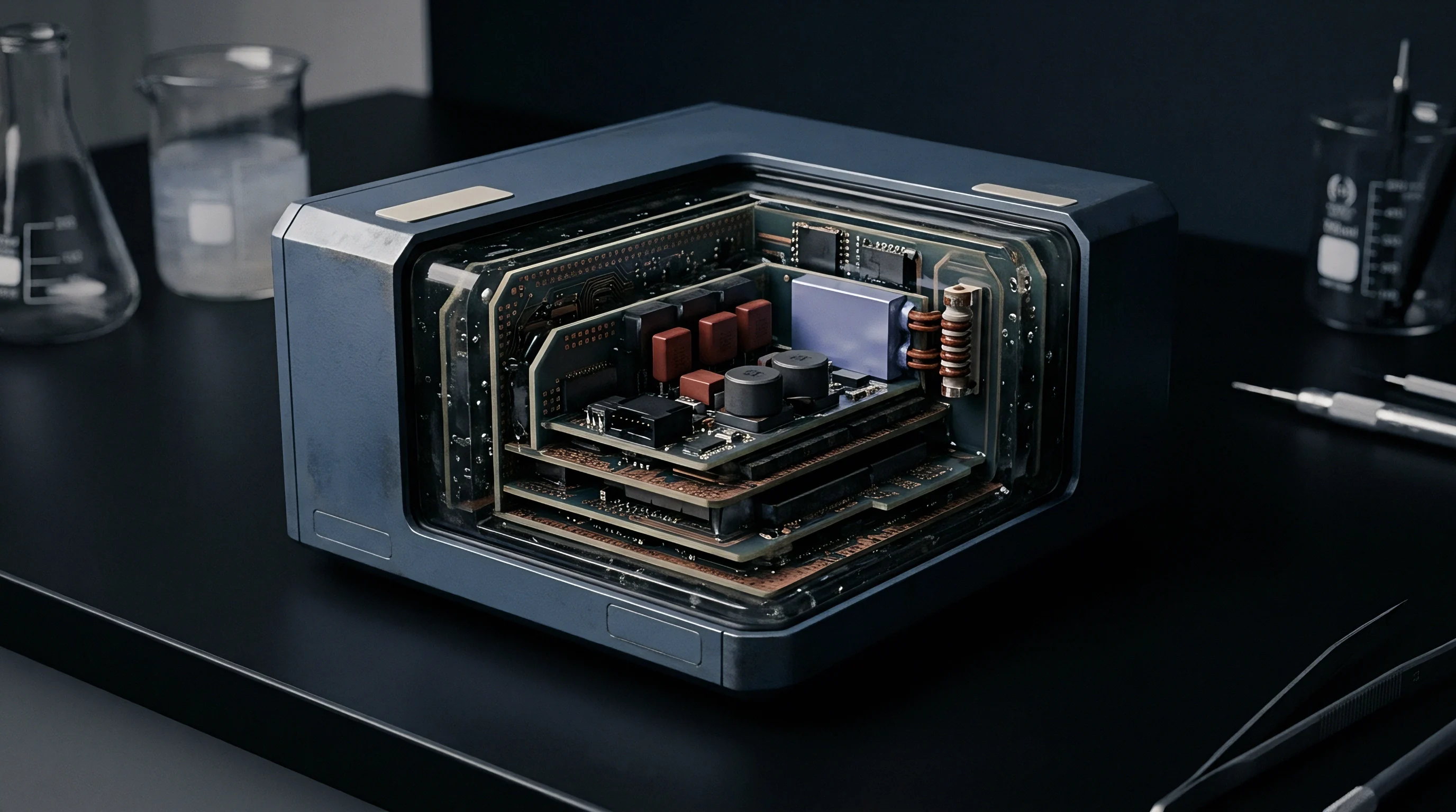
Conductive Noise Paths across Shared Power Buses
Direct electrical paths across power distribution networks represent a primary channel for cross-module interference. Multi-transmitter host architectures often power several RF modules from a central DC-DC switching regulator bus. High-frequency switching noise generated by pulse-width modulation regulators creates spectral harmonics extending into the tens of megahertz.
When radio modules draw pulsed current during transmission cycles, RF energy couples backwards into the power bus, creating a conductive path into neighboring transceivers.
Decoupling network design requires careful selection of capacitor values and dielectric types. Placing a standard 0.1-microfarad multilayer ceramic capacitor in parallel with a 10-picofarad capacitor at module power pins provides low impedance over broad frequency bands. The 0.1-microfarad capacitor decouples lower frequency switching transients, while the 10-picofarad capacitor exhibits self-resonance near 2.4 GHz, absorbing high-frequency RF ripple.
Using high-Q ceramic capacitors with COG or NPO dielectrics prevents capacitance drift over operating temperature extremes, maintaining power rail filtering integrity across industrial environment ranges.
| Regulatory Jurisdiction | Applicable Standard | Frequency Band | Detector Type | Field Strength / EIRP Limit | Multi-Transmitter Requirement |
|---|---|---|---|---|---|
| United States (FCC) | FCC Part 15 Subpart C (15.247) | 30 MHz ~ 10th Harmonic | Peak / Average | 54 dBuV/m at 3m (Restricted) / -20 dBc | Simultaneous transmission scan under KDB 996369 D04 |
| European Union (RED) | ETSI EN 300 328 v2.2.2 | 1 GHz ~ 12.75 GHz | Peak / RMS | -30 dBm (30 MHz – 1 GHz: -36 dBm) | Combinatorial intermodulation check required |
| Japan (MIC / Giteki) | Radio Law Enforcement Ord. Art. 2 | 30 MHz ~ 26 GHz | Peak / Average | -26 dBm / 2.5 uW per MHz | Host validation for co-located certified modules |
| Canada (ISED) | RSS-247 Issue 3 / RSS-Gen | 30 MHz ~ 5th Harmonic | Quasi-Peak / Peak | 54 dBuV/m at 3m (Restricted Bands) | RSP-100 simultaneous evaluation for host registration |
Power plane isolation strategies involve splitting internal PCB power layers into dedicated islands. A continuous power plane underlying multiple transceivers provides a low-impedance path for noise propagation across the entire board surface. Splitting the power plane into isolated islands connected only at single filtering points via ferrite beads isolates power noise within localized module zones.
Ferrite beads selected for power rail filtering must exhibit high complex impedance at target RF interference frequencies while handling maximum continuous DC load currents without magnetic core saturation.
Active regulator isolation provides superior power rail separation compared to passive LC filtering alone. Dedicated ultra-low-noise low-dropout regulators powering each radio module front end suppress power rail noise by over 60 dB at low frequencies and 30 dB at 1 MHz. The physical distance between the output of the low-dropout regulator and the RF module power input pin must be minimized to avoid picking up radiated noise from surrounding digital logic.
Enclosing power supply traces within internal PCB layers bounded by ground planes above and below forms a shielded stripline structure that eliminates power trace radiation.
When two co-located radio modules share a common power distribution bus, high-frequency switching transients act as conductive carrier vectors that bypass physical spatial isolation.
Printed circuit board stackup configuration dictates the overall electromagnetic performance of the integrated host. A six-layer PCB stackup optimized for multi-transmitter isolation places signal traces on Layer 1 and Layer 6, with continuous ground planes on Layer 2 and Layer 5, and power planes on Layer 3 and Layer 4. Ground planes immediately adjacent to top and bottom signal layers provide immediate return paths for microstrip transmission lines, minimizing loop areas and reducing radiated electromagnetic fields.
Omitting continuous ground planes under RF modules or routing digital traces across ground plane splits creates loop antennas that cause severe radiated compliance failures.
A rule of thumb dictates that doubling the distance between co-located antennas yields a fourfold reduction in near-field coupling power while adding conductive shielding cans over unshielded modules drops radiated cross-talk by at least twenty decibels.


Harmonics
Non-linear mixing between multiple simultaneous transmission carriers generates intermodulation products that fall into restricted frequency bands. When two or more radio transmitters broadcast concurrently, their fundamental frequencies combine inside non-linear host elements, such as output power amplifiers, protection diodes, rusty-bolt metallic junctions, or adjacent receiver front ends. The resulting intermodulation frequencies are calculated as f_IMP = |m f1 ± n f2|, where m and n are integers representing the harmonic order.
Third-order intermodulation products (2 f1 – f2 and 2 f2 – f1) pose severe compliance challenges because they lie close to fundamental operational frequencies and frequently exhibit high amplitude levels.
Evaluating multi-transmitter intermodulation requires accredited test laboratories to configure custom simultaneous transmission test modes. Standard single-transmitter compliance test firmware is insufficient for host-level evaluation. Automated test scripts must command all integrated modules to broadcast continuously at their maximum rated output power levels and worst-case duty cycles across various channel combinations.
Testing engineers sweep fundamental frequency pairs across lower, middle, and upper operating channels to identify channel combinations that produce worst-case intermodulation spikes inside restricted frequency bands defined by regulatory standards.

Why Do Intermodulation Products Evade Standard Pre-Scan Procedures?
Pre-scan procedures frequently fail to detect critical intermodulation products due to inadequate spectrum analyzer setup parameters and fast sweep times. Detecting narrow peak intermodulation spikes requires setting the resolution bandwidth (RBW) and video bandwidth (VBW) of the spectrum analyzer in strict accordance with standard specifications. Under FCC Part 15 and ETSI EN 300 328, radiated emission measurements above 1 GHz require an RBW of 1 MHz and a VBW of 3 MHz.
Running pre-scans with wider RBW settings or trace-averaging algorithms lowers the observed peak noise floor, masking low-level intermodulation spikes that later fail formal compliance sweeps when peak detectors are applied.
Sweeping speed limitations in automated test software can cause test equipment to skip intermodulation signals during rapid frequency scans. Continuous-wave or duty-cycled transmissions require sufficient dwell time at each measurement frequency step to capture peak emissions. If the spectrum analyzer sweeps past an intermodulation frequency while the transmitter is in an off-period of its duty cycle, the emission remains undetected until market surveillance audits perform continuous dwell scans.
Testing protocols must enforce minimum dwell times matching the maximum packet transmission interval of the host device.
| Active Transmitter Combination | Fundamental Frequencies | Calculated Intermodulation Order | Measured Spurious Output (dBm) | Chamber Compliance Status |
|---|---|---|---|---|
| Wi-Fi 2.4 GHz + LTE Band 4 | 2412 MHz (Wi-Fi) / 1710 MHz (LTE) | 2nd Order (f1 + f2 = 4122 MHz) | -34.5 dBm | Pass (ETSI EN 300 328 limit: -30 dBm) |
| Wi-Fi 5 GHz + Bluetooth LE | 5180 MHz (Wi-Fi) / 2402 MHz (BLE) | 3rd Order (2 f2 – f1 = -376 MHz; 2 f1 – f2 = 7958 MHz) | -28.2 dBm | Fail (Exceeds -30 dBm limit by 1.8 dB) |
| Sub-1 GHz + Wi-Fi 2.4 GHz | 915 MHz (Wi-SUN) / 2437 MHz (Wi-Fi) | 3rd Order (2 f1 + f2 = 4267 MHz) | -41.0 dBm | Pass (Margin: 11 dB under ETSI limit) |
| LTE Band 13 + Wi-Fi 2.4 GHz + BLE | 777 MHz (LTE) / 2462 MHz (Wi-Fi) / 2480 MHz (BLE) | 3rd Order Triple Mix (f1 + f2 + f3 = 5719 MHz) | -31.8 dBm | Fail (Fails FCC Restricted Band 5.35-5.46 GHz limit) |
Non-linear behavior inside passive mechanical structures introduces passive intermodulation (PIM) emissions that evade standard schematic analysis. Loose mechanical fasteners, oxidized metal-to-metal contacts between enclosure panels, and contaminated solder joints behave as Schottky diodes under high-intensity RF fields. When co-located antennas illuminate these non-linear mechanical junctions with high power, the junctions generate harmonic frequencies and intermodulation signals that radiate directly from the chassis structure.
Eliminating passive intermodulation requires strict cleanliness controls during mechanical assembly and applying consistent fastener torque specifications.
Intermodulation evaluation must account for modern wideband modulation schemes. Unlike narrow continuous-wave signals, wideband signals such as 80 MHz Wi-Fi 6E channels or 20 MHz LTE channels produce intermodulation products that spread over broad frequency bandwidths. The bandwidth of a third-order intermodulation product generated by two wideband signals is calculated as BW_IMP = 2 BW1 + BW2.
Spreading intermodulation power over a wider bandwidth reduces the peak spectral density observed in a 1 MHz RBW window, but increases total integrated power across restricted frequency bands, risking non-compliance under total radiated power evaluation standards.
Simultaneous transmission of Wi-Fi 6E at 5.8 GHz and cellular LTE Band 4 at 1.7 GHz generates a third-order intermodulation spike reaching -32 dBm inside the 2.4 GHz ISM band, failing ETSI EN 300 328 limits by 4 dB.

Chamber Turntable Protocols for Simultaneous Transmission
Radiated spurious emission testing of multi-transmitter hosts demands full three-dimensional spatial scanning inside accredited semi-anechoic or fully anechoic chambers. The host device rests on a non-conductive turntable situated three or ten meters from the measurement antenna. Standard test procedures rotate the turntable through 360 degrees while sweeping the measurement antenna height from one to four meters above the conductive ground plane.
This spatial scan maps the directional radiation pattern of all fundamental carriers and intermodulation products generated by the host assembly.
The turntable rotation protocol must account for phase alignment changes between multiple operating transmitters. As the host rotates, the relative phase distance between two integrated antennas changes relative to the fixed measurement antenna. At specific azimuth angles, radiated fields from both antennas combine constructively, causing localized spikes in measured field strength.
Identifying peak radiated intermodulation levels requires rotating the turntable at fine angular increments (no greater than 15 degrees) while step-scanning the entire frequency range. Fast continuous turntable rotation can miss narrow beamwidth intermodulation lobes.
Measurement antenna polarization switching is essential during host-level compliance scans. Radiated intermodulation products frequently exhibit orthogonal polarization relative to the fundamental carrier signals due to complex reflections inside the chassis and re-radiation from internal PCB traces. Test protocols must execute complete turntable sweeps in both horizontal and vertical measurement antenna polarizations.
The peak field strength recorded across all turntable azimuth angles, antenna heights, and polarizations represents the final compliance value submitted in the laboratory report.
Physical failure modes occurring during multi-transmitter co-location testing stem from specific RF and hardware interactions inside the integrated host housing.
- Intermodulation Spike Generation occurs when non-linear output stages of adjacent transmitters mix high-level RF signals, generating spurious products within restricted frequency bands.
- Chassis Cavity Resonance amplifies internal field strength at specific physical dimensions, creating localized radiated emission spikes that exceed spurious limit lines.
- Power Bus Cross-Coupling injects RF current ripple across shared DC voltage regulators, inducing high-frequency sideband noise into neighboring transceivers.
- Antenna Pattern Distortion alters the radiation envelope and impedance match of co-located module antennas, increasing back-reflected power into final output amplifiers.
- Ground Plane Current Loop Expansion converts shared PCB ground pours into secondary radiating structures, leaking high-frequency digital and RF noise past shielding cans.

Non-Linear RF Front-End Intermodulation Behavior
Active non-linear mixing within transceiver front-ends represents a primary source of simultaneous transmission interference. When a high-power cellular signal enters the antenna port of a nearby Bluetooth LE transceiver, the signal travels backwards through the Bluetooth bandpass filter and reaches the low-noise amplifier (LNA) or power amplifier (PA) output stage. The non-linear transfer function of the semiconductor junctions mixes the incoming cellular frequency with the Bluetooth operating frequency.
This process synthesizes new intermodulation frequencies that travel back out through the Bluetooth antenna, radiating into the environment.
Solid-state switches and digital attenuators inside multi-band RF front-ends contribute to non-linear harmonic generation under multi-transmitter stress. Integrated antenna switches utilizing pseudomorphic high-electron-mobility transistors (pHEMT) or silicon-on-insulator (SOI) processes exhibit non-linear ON-resistance and voltage-dependent OFF-capacitance. High RF voltages induced across switch terminals by a co-located transmitter drive the switch into non-linear operation, generating high-order harmonics and mixing products even when the host transceiver is in receive mode.
Field-effect transistor bias drift under thermal load further degrades RF front-end linearity. High ambient operating temperatures combined with internal power dissipation shift the quiescent bias point of power amplifier transistors closer to saturation. Operating closer to saturation reduces the third-order input intercept point (IP3) of the amplifier, accelerating the generation of intermodulation products.
Multi-transmitter host re-testing protocols must evaluate intermodulation performance after the device has reached thermal equilibrium under continuous full-power operating conditions.
Selecting low-loss, high-rejection external bandpass filters between the RF module output port and the host antenna connector provides an effective engineering solution for non-linear mixing. Installing a ceramic monoblock filter or thin-film surface acoustic wave (SAW) filter with 30 dB of rejection at adjacent transmitter frequencies prevents high-power unwanted signals from reaching active semiconductor junctions. However, adding external filters introduces insertion loss (typically 1.5 to 2.5 dB) into the desired transmission path, reducing fundamental output power and receiver sensitivity.
Failing to execute simultaneous transmission intermodulation scans during host integration leads to product recalls and border entry rejections when regulatory authorities discover non-compliant spurious emissions exceeding standard limits by over fifteen decibels.


Variance
Regulatory authorities enforce distinct administrative and technical pathways for certifying embedded devices containing integrated pre-approved radio modules. Under the Federal Communications Commission (FCC) framework in the United States, host integrators rely on Permissive Change procedures to update original modular grants. A Class I Permissive Change (C1PC) covers minor modifications that do not degrade RF characteristics or radiated emissions.
Integrating a modular transmitter into a new host housing where antennas operate within 20 centimeters of other transmitters exceeds C1PC boundaries, requiring a formal Class II Permissive Change (C2PC) filing executed by the original module grant holder or through a Change in FCC ID procedure.
European market access under the Radio Equipment Directive (RED) 2014/53/EU follows a self-declaration or Notified Body assessment pathway. Unlike the rigid grant structure of the FCC, the manufacturer of the final radio equipment assumes full legal responsibility for compliance under RED Article 3.2 (efficient use of radio spectrum). When integrating multiple pre-certified modules into an industrial host, the host manufacturer cannot simply aggregate individual CE Declarations of Conformity.
The combined equipment must undergo host-level evaluation against harmonized standards (such as ETSI EN 300 328, EN 301 893, and EN 301 489-17) to verify that multi-transmitter interaction does not generate non-compliant spurious emissions.

Permissive Change Thresholds in Global Jurisdictions
Filing requirements vary across international certification bodies when host geometry alters radio operating conditions. Innovation, Science and Economic Development Canada (ISED) aligns closely with FCC guidance under publication RSP-100, requiring a Class 2 Permissive Change or Category I mini-modification filing when host co-location introduces simultaneous transmission modes not covered in the original modular approval. The table below compares permissive change classification rules, host re-testing mandates, and technical filing requirements across key global jurisdictions.
Japan’s Ministry of Internal Affairs and Communications (MIC / Giteki) applies strict rules regarding modular host binding. Modular approvals in Japan are tied to specific construction type certifications. If an industrial host integrates multiple radio modules in a layout that modifies original antenna gain parameters or adds concurrent transmission combinations, the final assembly requires host-level validation testing.
Technical regulations force host manufacturers to retain compliance test records in their technical construction file, accessible for MIC market surveillance audits.
China’s State Radio Regulation Commission (SRRC) enforces host binding regulations that restrict modular approval usage. SRRC modular certificates explicitly declare whether a module is approved as a complete standalone unit or restricted for integration within specific host types. Host integration that introduces simultaneous transmission between cellular and Wi-Fi modules requires submitting the complete host device for accredited in-country testing at designated national laboratories in Beijing or Shenzhen.
Relying solely on individual module SRRC certificates for custom industrial host assemblies results in immediate customs clearance blocks.
South Korea’s National Radio Research Agency (RRA / KC Mark) enforces strict registration rules for host radio equipment. Under KC regulations, integrating a pre-approved wireless module into a new host housing requires updating the conformity registration. If co-located transmitters broadcast concurrently, the host device must undergo full EMC testing under KS X 3124 and RF testing under relevant KS X standards to confirm that intermodulation products satisfy national technical requirements.
FCC KDB 996369 D04 clause 3.2 removes modular approval immunity whenever host enclosure geometry places internal antennas within 20 centimeters of each other.

Host Manufacturer Liability Boundaries and Grant Limits
Host manufacturers often misunderstand the legal protections afforded by modular radio approvals. An OEM purchasing a certified Wi-Fi module receives a device compliant with standalone regulatory limits. The modular grant explicitly defines the boundary of compliance: approved antenna types, maximum allowed antenna gains, minimum separation distances, and standalone operational modes.
The moment an OEM installs that module into a custom host enclosure alongside a cellular transceiver, the OEM assumes the legal role of the radio equipment manufacturer under regulatory enforcement law.
Regulatory enforcement agencies hold the final host manufacturer legally liable for non-compliant emissions released into the market. If market surveillance authorities select an industrial gateway from retail or industrial distribution channels and discover radiated intermodulation products exceeding statutory limits, enforcement penalties target the host manufacturer listed on the product label, not the supplier of the radio module. Penalties include mandatory market withdrawals, fines reaching hundreds of thousands of dollars, and formal revocation of market authorization.
Host manufacturers must maintain comprehensive compliance decision matrices within their engineering files to defend permissive change classifications. The following decision checklist guides engineering practices when determining regulatory filing requirements for integrated host hardware.
- Antenna Separation Verification confirms whether physical spacing between all co-located antennas exceeds 20 centimeters under final assembly conditions.
- Antenna Gain Comparison verifies that fitted host antennas do not exceed peak gain values specified in the original modular grant reports.
- Simultaneous Transmission Mapping identifies all potential concurrent broadcast combinations allowed by system control software.
- Spurious Emission Pre-Scan Validation evaluates whether host-level intermodulation products remain below statutory limit lines with at least 6 dB of passing margin.
- Permissive Change Filing Authorization secures formal written permission from the original module grant holder to execute Class II Permissive Changes under their FCC ID.
Contractual agreements between host manufacturers and radio module suppliers must address grant update procedures. Many module vendors refuse to allow third-party OEMs to file Class II Permissive Changes under the vendor’s original FCC ID due to liability concerns. In such cases, the host manufacturer must execute a Change in FCC ID filing under FCC Part 2.933, creating a new FCC ID owned entirely by the host manufacturer.
Owning the FCC ID allows the host manufacturer to file necessary permissive changes and control certification updates independently.
Module suppliers routinely assure integration teams that modular certificates eliminate all host-level RF testing requirements, neglecting to mention that simultaneous transmission conditions legally void single-module exemption clauses across every major global market.
Analyzing host integration files determines whether existing modular documentation covers final industrial enclosure layouts or requires supplementary Class II Permissive Change filings before volume manufacture.


Arithmetic
Budgeting host-level re-testing campaigns demands accurate financial and schedule modeling. Direct costs incurred at accredited testing laboratories form the primary expense of a certification program. Accredited semi-anechoic testing chambers command hourly rates ranging from $450 to $850 per hour depending on geographic location, chamber size (3-meter versus 10-meter), and required frequency range (up to 40 GHz or 200 GHz for millimeter-wave devices).
A comprehensive multi-transmitter host evaluation campaign typically consumes 40 to 80 hours of active chamber time, translating to direct testing fees between $18,000 and $68,000 per product variant.
Indirect costs equal or exceed direct laboratory fees when campaigns run into unexpected delays. Custom test software development, specialized non-conductive mounting fixtures, sample preparation, in-country local representative fees, and administrative regulatory filing fees add substantial financial overhead. Furthermore, failing an initial chamber sweep introduces re-test loops: diagnostic time, circuit redesign, PCB re-spin, and re-booking scarce laboratory chamber slots.
The table below outlines a typical landed cost model for a multi-transmitter industrial host device undergoing global certification across four major economic markets.

Laboratory Chamber Hour Allocation and Test Sizing
Sizing chamber time allocation requires breaking down the test plan into discrete execution phases. Initial setup and system calibration consume the first four to eight hours of chamber time. RF test engineers verify cable losses, test antenna factors, turntable positioning controls, and signal generator synchronization.
Once calibrated, single-transmitter baseline verification scans require approximately two hours per active radio technology across three operating channels (low, mid, high).
Simultaneous transmission intermodulation evaluation represents the most time-intensive testing phase. Testing a triple-radio host (Wi-Fi 6E, Bluetooth LE, LTE-M) requires evaluating multiple frequency channel matrix combinations. If Wi-Fi operates across 3 channels, BLE across 3 channels, and cellular across 5 frequency bands, the combinatorial matrix yields 45 distinct operational states.
Evaluating each operational state across 360 degrees of turntable rotation and two antenna polarizations demands strict prioritization. Test engineers utilize automated software to perform rapid pre-scans across all 45 combinations, identifying the top three worst-case emissions for deep compliance dwell sweeps.
| Testing Phase / Certification Scope | Required Chamber Hours | Laboratory Rate per Hour (USD) | In-Country Agent / Filing Fee (USD) | Total Landed Expense per Market (USD) |
|---|---|---|---|---|
| United States (FCC C2PC / Part 15 / WWAN) | 36 Hours | $550 | $2,500 (TCB Filing Fee) | $22,300 |
| European Union (RED Article 3.1b / 3.2 CE) | 48 Hours | $600 | $3,800 (Notified Body Review) | $32,600 |
| Japan (MIC / Giteki Host Validation) | 24 Hours | $700 | $4,200 (RCB Certificate + Local Agent) | $21,000 |
| China (SRRC In-Country Testing & Binding) | 40 Hours | $500 (Fixed Test Package) | $6,500 (SRRC Agency & Translation) | $26,500 |
Sample preparation requirements multiply hardware logistics budgets. Accredited laboratories require at least two fully functional host units per product variant: one sample configured for conducted RF testing with temporary coaxial pigtails soldered to internal RF traces, and one pristine sample for non-destructive radiated spurious emissions testing. Cellular devices often require specialized test SIM cards and call-box communication testers (such as Rohde & Schwarz CMW500 or Anritsu MT8820C) to establish active cellular links during turntable sweeps, adding instrument rental fees to the laboratory bill.
Custom test mode firmware development represents a hidden labor cost often overlooked during project scheduling. Firmware engineers must write low-level control code that allows test lab operators to manipulate radio parameters via simple serial terminal commands (UART or USB). The test script must enable setting operating frequency, data rate, modulation type, output power level, and continuous transmission duty cycles independently for each integrated radio.
Delaying test firmware delivery stalls laboratory testing, incurring idle chamber standby fees averaging $250 per hour.

Global Certification Financial Modeling across Key Markets
Staging market entry plans optimizes cash flow during global deployment campaigns. Submitting hardware to the FCC and European Union simultaneously provides the fastest path to initial revenue, opening markets representing over 50 percent of global industrial automation demand. Secondary market entry into Japan, South Korea, China, and Brazil should be scheduled after obtaining initial FCC and CE test reports.
Laboratories in secondary markets often accept existing FCC and CE test data to satisfy portions of local technical requirements, reducing local chamber hours and cutting overall certification expenditures.
In-country representation and administrative maintenance fees add ongoing annual overhead to global product lines. Markets such as South Korea, Brazil (ANATEL), and Mexico (IFT) require foreign manufacturers to retain local registered agents who hold legal ownership of certificates. Local agent fees average $1,500 to $3,500 per year per market.
Furthermore, certification maintenance fees apply when standards undergo periodic updates, requiring technical file reviews every three to five years to maintain valid market access authorization.
Compiling a complete technical submission package ensures smooth TCB and Notified Body reviews. The following list outlines mandatory documentation elements required within a multi-transmitter host integration dossier.
- Host Block Diagram and Schematic Set detailing power distribution paths, ground connections, and high-speed digital interface signal routing.
- RF Antenna Operational Description specifying antenna types, manufacturer part numbers, peak gain tables, and physical separation distances inside the host chassis.
- Simultaneous Transmission Test Report presenting chamber measurement data, turntable polar plots, and peak spurious emission tables under simultaneous broadcast modes.
- Modular Grant Documentation incorporating copies of original modular certificates, FCC IDs, IC numbers, and original modular operational boundaries.
- Product Label Schematics illustrating physical placement of FCC ID, IC registration, CE mark, UKCA mark, and KC logo on the outer host housing.
Computing landed compliance cost profiles requires combining laboratory hourly rates, filing agency fees, and re-test probability factors across multi-transmitter industrial hardware configurations.
Re-testing cost contingency funds should be allocated at 20 to 30 percent of the total compliance budget. If a device fails radiated emissions due to an unforeseen intermodulation spike, the contingency fund covers diagnostic chamber hours (typically 8 to 16 hours), rapid prototype PCB modifications, and formal re-testing sweeps. Project schedules must incorporate a four-week buffer to accommodate potential re-test loops without impacting commercial shipment commitments.
Standard engineering contracts stipulate that regulatory compliance verification requires documented evidence of simultaneous transmission evaluation executed in accordance with ANSI C63.26 and FCC KDB 996369 guidelines before commercial shipment authorization is granted.


Oversight
Market surveillance mechanisms enforced by national communications authorities continuously monitor compliance of commercial radio equipment. Regulators in the United States, European Union, Japan, and South Korea purchase off-the-shelf industrial devices from distributor inventories, subjecting them to complete accredited laboratory re-testing. Surveillance programs focus heavily on multi-transmitter devices, as historical audit data reveals high rates of non-compliance stemming from unmodeled intermodulation products and unauthorized firmware modifications.
Discovering non-compliant radiated emissions triggers immediate administrative enforcement actions against the host manufacturer.
Factory production control audits represent another layer of regulatory oversight. Under European Union RED requirements and ISO 17025 laboratory quality frameworks, manufacturers must ensure that mass-produced units maintain identical electromagnetic characteristics to the sample evaluated during original type-examination testing. Variations in surface-mount component tolerances, second-source switching regulator substitutions, PCB dielectric constant drift, or automated solder reflow quality can alter high-frequency parasitic parameters, pushing production units past statutory emission limits.

Post-Market Surveillance and Regulatory Audit Risks
Supply chain component substitutions pose severe ongoing compliance risks for integrated host devices. When component shortages force engineering teams to replace passive components, RF switches, or voltage regulators with alternative second-source parts, the electromagnetic profile of the device changes. Substituting a low-dropout regulator with an alternative part exhibiting lower power supply rejection ratio allows high-frequency switching noise to couple into the radio transceiver, generating new radiated emission spurs.
Host manufacturers must enforce strict Change Management protocols, evaluating the electromagnetic impact of every component substitution before authorizing production release.
Regulators enforce clear corrective action escalation pathways when field units fail compliance audits. Minor administrative errors, such as incomplete user manual safety statements or misaligned label typography, prompt formal warning letters requiring corrective action within 30 days. Technical non-compliance, such as radiated intermodulation emissions exceeding statutory limits by over 3 dB, triggers mandatory sales freezes, public safety recall notices, and customs import blocks.
Resolving a technical non-compliance enforcement action requires redesigning hardware, re-testing the complete host assembly, and re-submitting technical construction files across every market where the product is sold.
The financial impact of market surveillance enforcement extends far beyond direct regulatory fines. Recalling thousands of industrial gateways installed across critical infrastructure projects involves massive field service labor costs, breach-of-contract penalties from enterprise customers, and lasting damage to corporate brand reputation. Ensuring rigorous host-level re-testing during initial product development represents a small fraction of the cost incurred when handling a post-market recall campaign.

Firmware Power Table Controls in Field Deployment
Software-defined power tables control maximum output power levels across operational channels and modulation modes. Integrated radio modules rely on host firmware to load calibrated power tables into internal register memory upon system boot. If host software development teams modify power table values to boost wireless range or improve link margins in dense industrial environments, they risk exceeding maximum EIRP limits established during modular certification.
Over-driving output power amplifiers accelerates non-linear distortion, compounding intermodulation emission levels exponentially.
Firmware architecture must incorporate secure locking mechanisms to prevent unauthorized manipulation of RF power settings. Regulatory standards, including FCC Part 15 subpart E (UNII band software security requirements under KDB 594280) and ETSI EN 303 645 cybersecurity guidelines, require manufacturers to protect radio configuration software against end-user modification. Encrypting firmware binaries, enforcing cryptographically signed firmware update packages, and locking memory access registers prevent third-party open-source software distributions or field technicians from altering calibrated RF power tables.
Dynamic Frequency Selection (DFS) compliance in 5 GHz Wi-Fi bands demands strict coordination between host firmware and co-located cellular modules. When a 5 GHz Wi-Fi module operates in DFS frequency bands (5.250 ~ 5.350 GHz and 5.470 ~ 5.725 GHz), it must continuously monitor the channel for radar signals. High-power transmission bursts from a co-located cellular module can blind the Wi-Fi receiver, causing it to miss radar detection pulses and fail statutory DFS compliance audits.
Host firmware must implement co-existence arbitration protocols (such as packet traffic arbitration over dedicated GPIO lines) to pause local transmissions during DFS radar monitoring windows.
Continuous compliance verification across the product lifecycle requires incorporating routine RF spot-checking into factory End-of-Line (EOL) production testing. Equipping manufacturing lines with simplified RF test fixtures (such as shielded test boxes connected to low-cost spectrum analyzers or power meters) allows production teams to verify fundamental output power and harmonic levels on a percentage of manufactured units. Catching component assembly defects or detuned antenna circuits on the factory floor prevents non-compliant hardware from entering global distribution channels.
Quality management systems must maintain clear traceability linking product serial numbers, installed hardware revisions, loaded firmware builds, and corresponding compliance test reports. When regulatory auditors request technical construction documentation for a specific field unit, the host manufacturer must deliver complete evidence proving that the specific serial number and hardware build match the certified host configuration. Maintaining precise compliance documentation safeguards international market access and defends corporate reputation against enforcement actions.