Navigating Modular FCC Approvals for Embedded Wireless Hardware Devices
Pre-certified FCC modular grants eliminate fundamental radio testing but require strict host trace adherence, exposure compliance, and Part 15B verification.


Grant
Federal Communications Commission authorization under Title 47 of the Code of Federal Regulations Part 15 sets strict boundaries for integrating wireless transmitters. A pre-certified radio module carries an equipment authorization identifier that transfers to the host device, provided operating limits are met. Using an approved transmitter module saves the host manufacturer from repeating fundamental transmitter tests under Part 15C or Part 15E.
However, the finished product must still be evaluated as an unintentional radiator under Part 15B to ensure microcontrollers, power supplies, and digital bus lines stay below legal field strength limits for noise.
Eight Rules of Part Fifteen Section Two Twelve
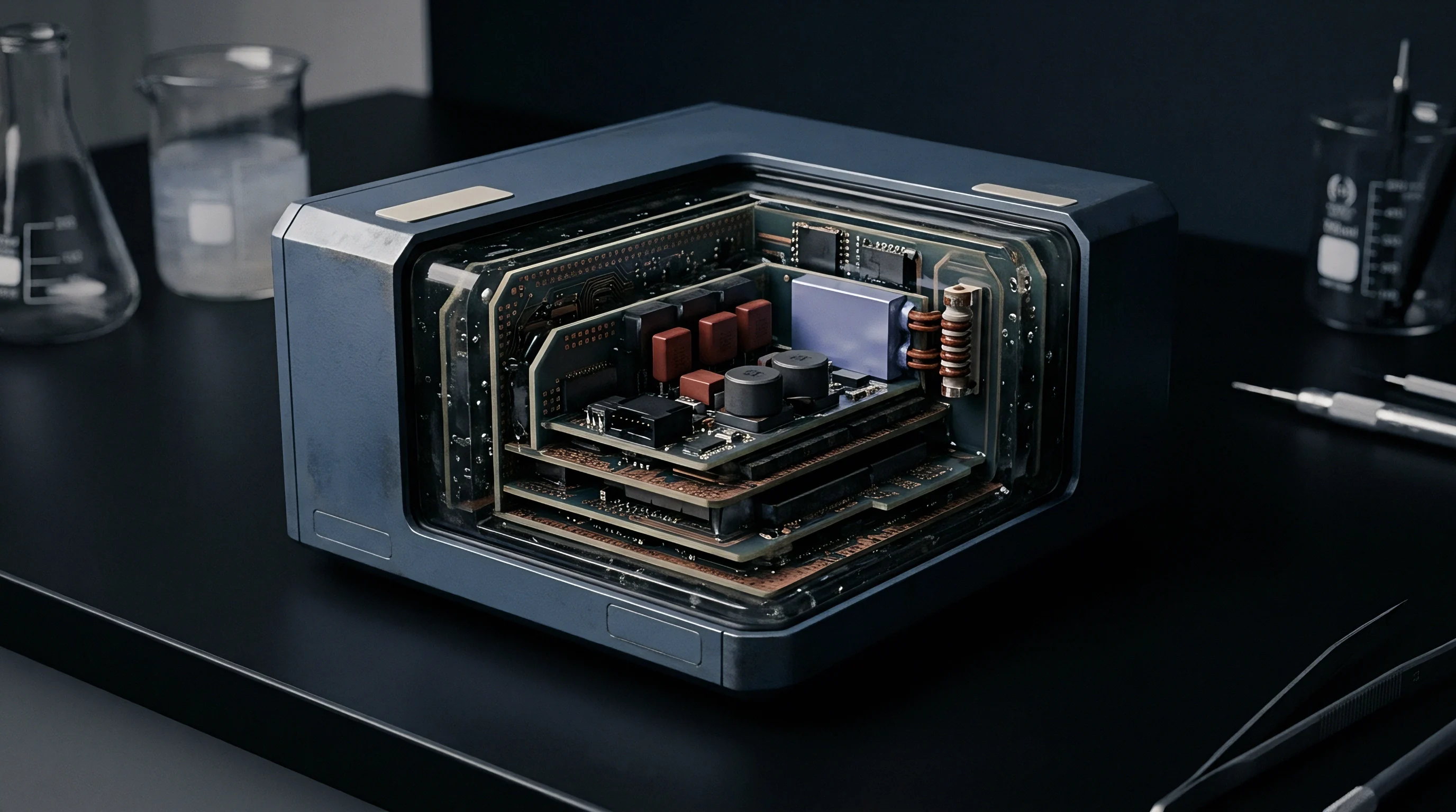
Title 47 CFR Section 15.212 lays out the technical criteria for modular transmitter approval in explicit physical terms. The radio frequency section must have its own shielding to prevent coupling with host circuitry. Buffered modulation and data inputs keep excessive data rates or over-modulation from pushing spurious emissions past legal limits.
Internal voltage regulation keeps operating power steady despite fluctuations in battery state or host supply rails. Finally, the antenna must connect via a permanently attached radiator, a unique coupler, or a specific trace layout documented in the filing dossier.
Stand-alone testing requires the radio module to pass all spurious emission and bandwidth tests on an open bench without a host enclosure, proving the module maintains full control over its output power regardless of external bus activity. The physical hardware must carry a permanently affixed label showing its FCC identifier or use compliant electronic labeling under Section 2.935. Additionally, the grantee must provide integration instructions specifying power supply tolerances, antenna gain limits, and co-location restrictions.
The equipment authorization transfers to the final enclosure only when every physical integration parameter matches the original filing conditions.

Full versus Limited Module Authorizations
A Full Modular Approval allows integration into any host platform, as long as the integrator follows the layout and antenna rules in the integration manual. A Limited Modular Approval comes into play when the radio assembly lacks one or more of the eight physical requirements ~ such as an on-board shield or internal voltage regulator. A limited grant confines deployment to specific host environments evaluated directly by the grantee or through joint laboratory filings.
The host integrator assumes compliance responsibility for operational conditions omitted on the module board itself:
- Regulated Supply Voltage delivers clean direct current from the host motherboard when the transmitter lacks on-board low-dropout regulators.
- Dedicated Metal Enclosure provides external shielding whenever an unshielded module operates within a metallic host chassis.
- Direct Firmware Lockout locks regional frequency selection and maximum conducted output power across commercial firmware builds.
- Specific Platform Authorization restricts module installation to predetermined host motherboards validated through formal lab test reports.
In short, a modular grant covers the radio circuit itself, not the final product packaging built around it.


Coupling
Radio frequency energy from an embedded transmitter interacts with nearby conductive surfaces and human tissue. Title 47 CFR Section 2.1091 and Section 2.1093 govern human exposure to these RF fields. Equipment operating more than 20 centimeters from the body is classified as mobile hardware, allowing compliance verification through Maximum Permissible Exposure power density calculations.
Device placement within 20 centimeters of human tissue classifies the hardware as portable, triggering Specific Absorption Rate testing in calibrated liquid phantoms.

How Does Antenna Redesign Invalidate Modular Coverage?
Swapping antennas changes peak radiated energy and directivity patterns. A modular grant covers operation only with the antenna types and peak gains evaluated in the original certification. An integrator can replace a certified dipole with another dipole of equal or lower peak gain across the authorized bands without submitting new test data.
However, replacing a dipole with a patch or printed inverted-F antenna alters the field distribution enough to require a permissive change filing, regardless of nominal gain numbers.
Routing antenna traces on the host board can introduce unwanted parasitic capacitance and impedance discontinuities along the microstrip. If a modular grant relies on a specific trace-to-connector design, the host board layout must match the dielectric constant, layer stackup, trace width, and ground clearance detailed in the integration manual. Even minor changes in substrate thickness alter the 50-ohm transmission line impedance, creating reflections that drive up harmonic emissions during chamber testing.
| Operating Class | Separation Distance | Primary Assessment Metric | Standard Regulatory Rule | Laboratory Requirement |
|---|---|---|---|---|
| Mobile Equipment | Equal to or greater than 20 cm | Power Density (mW per square cm) | 47 CFR Section 2.1091 | Calculated numerical exposure dossier |
| Portable Equipment | Less than 20 cm | Specific Absorption Rate (W per kg) | 47 CFR Section 2.1093 | Automated phantom liquid measurement |
| Co-located Radios | Variable enclosure spacing | Composite Exposure Ratio sum | KDB Publication 447498 | Simultaneous transmission intermodulation sweep |

Specific Absorption Rate Thresholds and Co-Location
FCC Knowledge Database Publication 447498 provides formulas to determine whether low-power transmitters qualify for SAR test exclusion. Exemption depends on conducted power levels, operating frequency, and physical distance from the user. Transmitters that fall outside these exemption thresholds must undergo physical testing using liquid phantoms across multiple device orientations.
Co-location occurs when an embedded design houses multiple transmitters radiating simultaneously within one enclosure. Combining a Wi-Fi transceiver, a cellular modem, and a Bluetooth subsystem produces non-linear intermodulation products. The host manufacturer calculates the Composite Exposure Ratio by adding together the exposure ratios of all active links.
If the total exceeds unity, the complete assembly requires chamber testing under simultaneous transmission modes.
KDB Publication 447498 mandates Specific Absorption Rate evaluation whenever simultaneous transmission exposure ratios aggregate above unity.
Skipping simultaneous transmission evaluations during prototyping can lead to impounded shipments at customs and mandatory retesting before products can be released to market.


Solder
Surface-mount radio modules attach to host motherboards through land grid array pads or castellation contacts. This mechanical joint carries both the direct current power supply and the high-frequency RF signal path. Solder paste volume, stencil aperture design, and reflow temperature profiles dictate the quality of electrical grounding between the module’s bottom ground plane and the host board’s internal return layers.
Voids in these ground solder joints raise common-mode RF currents across the host circuit board.

Trace Layout Rules and Connector Geometries
Engineers route RF traces from castellation pads to antenna connectors using microstrip or coplanar waveguide geometries. Any shift in copper weight or dielectric substrate material alters the velocity factor and characteristic impedance. The Federal Communications Commission requires integrators to implement published trace design parameters without modification, as even small variations in solder mask thickness over an RF microstrip change distributed capacitance and degrade return loss.
| Physical Layout Parameter | Nominal Design Target | Allowed Deviation Margin | Emissions Failure Mechanism |
|---|---|---|---|
| Characteristic Impedance | 50.0 ohms | Plus or minus 2.5 ohms | Standing waves elevate harmonic spikes |
| Trace Width (Microstrip) | 0.45 mm (FR-4 substrate) | Plus or minus 0.02 mm | Mismatched line degrades transmitter return loss |
| Ground Via Spacing | 1.20 mm pitch | Maximum 1.50 mm pitch | Substrate resonance leaks radiated energy |
| Dielectric Height | 0.20 mm core thickness | Plus or minus 10 percent | Phase velocity shift shifts notch filter points |
Why Do Host Power Rails Corrupt Radiated Emissions?
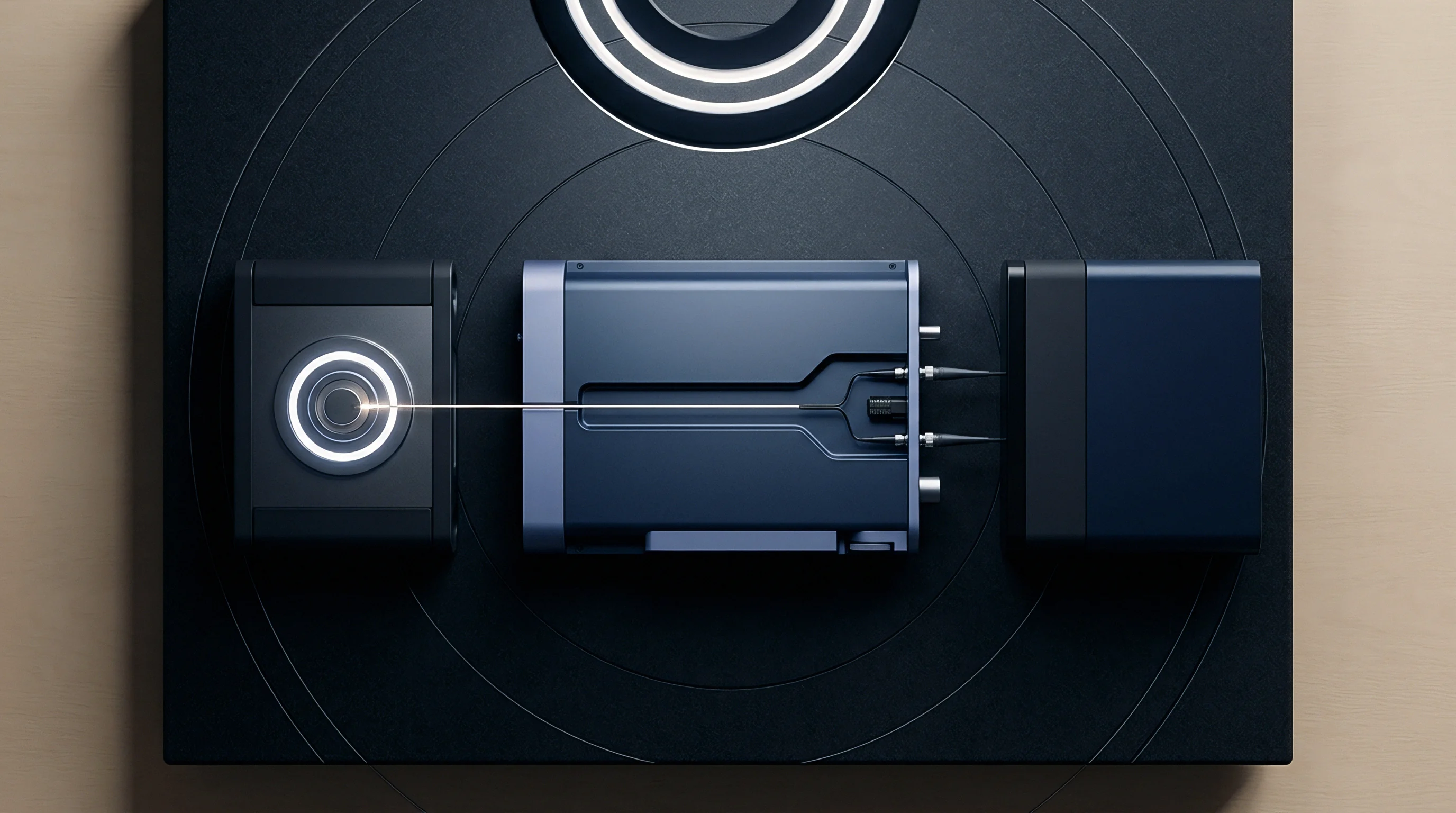
Switching regulators on the host board produce rapid voltage transients and high-frequency current loops. When these switching frequencies couple into the power input pins of a wireless module, the noise modulates onto the RF carrier. This added phase noise degrades spectral purity and produces intermodulation spurs that fail Part 15C band-edge compliance.
Decoupling capacitors with low equivalent series resistance need to sit directly adjacent to the power input pins, backed by solid ground planes beneath power traces to eliminate return loops. Poor decoupling forces high-frequency noise currents across enclosure seams, effectively turning plastic housings and attached cables into unintended dipole antennas during chamber scans.
- Substrate Material Verification ensures FR-4 or high-frequency laminate matches the dielectric loss tangent documented inside the module integration dossier.
- Time-Domain Reflectometry Inspection confirms 50-ohm characteristic impedance across all board transitions, preventing phase distortion along the antenna launch trace.
- Thermal Profile Calibration prevents solder bridging and dry joints beneath unexposed ground pads located on the central belly of the module.
- Near-Field Probe Scanning detects local switching noise leaking from host inductors into the transmitter input pins prior to compliance testing.
Phase distortion degrades spectral purity when RF trace return paths encounter discontinuities in the reference ground plane.
Minor trace length extensions are often assumed to align with application notes without changing radiated field strength.


Variance
Modifications to an authorized wireless sub-assembly fall under the permissive change rules in 47 CFR Section 2.1043. When host manufacturers alter passive components, firmware parameters, or antenna configurations, regulatory filings preserve legal marketing status. Minor component changes that do not affect basic radio characteristics or spurious emissions qualify as Class I Permissive Changes, requiring no formal filing with the Commission.

Permissive Change Classification Criteria
A Class II Permissive Change is required when modifications degrade spurious emissions, increase thermal dissipation, or alter human exposure profiles without exceeding legal limits. Replacing an external whip antenna with an internal trace antenna of identical peak gain triggers a Class II filing because the spatial field distribution changes. The grantee must submit lab test reports to a Telecommunication Certification Body detailing radiated spurious emissions and exposure data for that specific host.
| Filing Classification | Hardware Modification Scope | Laboratory Test Scope | Submission Requirement |
|---|---|---|---|
| Class I Permissive Change | Non-frequency-determining passive component shifts | Internal verification records | No formal filing required |
| Class II Permissive Change | Antenna pattern shifts, enclosure proximity, co-location | Radiated spurious and exposure sweeps | Formal TCB report submission |
| Change in Identification | Relabelling certified radio without circuit changes | Documentary reconciliation only | Administrative filing under Section 2.933 |
| New Equipment Authorization | Frequency band expansion, power amplifier addition | Full fundamental and harmonic characterization | Complete original grant process |
Change in Identification Filing Mechanics
Original equipment manufacturers frequently rebrand pre-certified wireless modules under their own name to safeguard supply chain details. Title 47 CFR Section 2.933 allows for this Change in Identification. The applicant submits a permission letter from the original grantee, external photographs of the newly labeled hardware, and a formal declaration confirming that the internal radio design remains identical to the certified device.
A Class II Permissive Change dossier requires specific administrative and technical exhibits:
- Original Grantee Permission Letter grants legal authorization for the third-party host integrator to file against the established FCC identifier.
- Radiated Spurious Test Report presents formal anechoic chamber measurements demonstrating compliance across all harmonic frequencies up to the tenth harmonic.
- Specific Absorption Rate Dossier confirms that energy absorption levels stay below the 1.6 watts per kilogram limit inside human tissue models.
- Updated Operational Description clarifies all host integration constraints, internal cable routing paths, and antenna placement drawings.
Section 2.1043 of the Federal Communications Commission rules places full legal and financial responsibility for Class II permissive change filings on the grantee of record.


Schedule
Market access timelines place compliance testing on the critical path. While a full transmitter certification campaign demands extensive laboratory chamber time, integrating a pre-approved module shortens testing to a focused validation window. Host manufacturers must still budget time for Part 15B unintentional radiator scanning, spot-checking radiated spurious emissions, and administrative review queues at accredited Telecommunication Certification Bodies.

Laboratory Queue Dynamics and Retest Buffers
Accredited electromagnetic compatibility test houses handle volatile queues driven by seasonal product cycles, making advance booking windows of three to six weeks necessary for anechoic chamber access. When unexpected harmonic radiation from host microcontrollers spills into transmitter bands, fix attempts require PCB re-spins, component changes, and follow-up chamber sweeps.
A typical modular integration campaign takes two to four weeks of laboratory time. Engineering teams usually schedule extra buffer weeks to address any emissions issues uncovered during preliminary pre-scans.
Unintentional radiation from host digital buses accounts for the majority of initial chamber test failures during modular integration programs.

Host Verification Costs and Market Filing Windows
Financial planning for wireless launches must account for lab testing fees, certification body reviews, and administrative filing expenses. A full transmitter authorization under Part 15C routinely reaches twenty-five thousand dollars, whereas host verification using a pre-certified module generally costs between four thousand and eight thousand dollars. Once approved, the host technical documentation file must remain available for regulatory audit throughout the product’s commercial lifecycle.
- Pre-Scan Diagnostic Evaluation identifies radiating PCB traces and decoupling deficiencies before entering the accredited compliance chamber.
- Formal Unintentional Radiator Testing generates the calibrated Part 15B measurement report for the final commercial product enclosure.
- Radiated Spurious Spot-Checking confirms that co-located radios and internal antennas do not generate unmapped intermodulation spurs.
- TCB Dossier Submission delivers technical exhibits to the certifying body for administrative review and official database upload.
Host manufacturers allocate budget across pre-compliance scans, formal Part 15B verification, and Telecommunication Certification Body filing fees to keep hardware releases on schedule.