FCC Part 15 Subpart C Radio Module Sourcing Basics
FCC Part 15 Subpart C module sourcing hinges on verifying full modular grants, honoring antenna trace geometries, and testing host unintentional emissions.


Shield
Spectrum analyzers sweep the second harmonic of an unshielded 2.4 GHz oscillator into immediate non-compliance across a thirty-meter open area test site. The bench captures these parasitic radiation paths long before any hardware reaches a border. For an integrator, the regulatory line is clear: intentional radiators governed by Title 47 of the Code of Federal Regulations, Part 15, Subpart C, require formal equipment authorization before marketing or commercial operation in the United States.
Laying down a bare transceiver IC leaves transmitter testing, documentation, and FCC filings entirely on the host manufacturer. Sourcing a pre-certified module moves that boundary to the edge of the bought component.
Federal rules set out specific criteria for an assembly to carry its own FCC identifier. Incoming inspection looks for metal cans, buffered lines, integrated voltage regulation, and onboard antennas. Under Section 15.212, satisfying eight specific conditions allows host integrators to skip fundamental transmitter testing entirely.
Missing even one requirement drops the part to limited modular status or an uncertified subassembly.
Section 15.212 of Title 47 voids a full modular grant whenever the host PCB copper ground acts as the missing half of the radio enclosure shield.
Verifying equipment authorization starts with the physical package. Full modular approval requires a solid metal shield soldered over the transceiver circuitry, frequency synthesis network, and front-end filters. That barrier keeps local oscillator leakage inside and isolates internal switching transients from host PCB traces.
Unshielded modules arrive only with limited modular approval, which pushes coupling analysis and host-level emissions testing straight into the product’s final production file.
| Authorization Pathway | Grantee Ownership | Physical Shielding Mandate | Host Retesting Burden | Market Entry Lead Time |
|---|---|---|---|---|
| Full Modular Approval | Module Vendor | Integrated metal enclosure present | Part 15B host verification and spot checks | Two to four weeks |
| Limited Modular Approval | Module Vendor or Host Maker | Partial or absent shield | Full radiated emissions on host enclosure | Six to ten weeks |
| Full Host Certification | Host Product Integrator | Open circuit or bare chip integration | Complete transmitter qualification | Ten to sixteen weeks |
Buffering the modulation and data inputs isolates the transmit chain from bus activity. Driving an unbuffered mixer straight from a microcontroller running fast SPI or UART signals widens occupied bandwidth as soon as clock edges degrade. Section 15.212 requires internal buffering to prevent over-modulation from excessive input drive or rogue bus states.
Integrated power supply regulation also decouples the power amplifier from battery fluctuations; internal low-dropout regulators hold the supply rail steady across discharge cycles to keep harmonics within statutory limits.
Failure modes multiply when module buyers mistake cost reduction for regulatory compliance:
- Unshielded inductor leakage generates radiated spurs that exceed Section 15.209 general field strength limits during burst operation.
- Unbuffered data inputs distort modulation sidebands whenever host firmware increases clock line slew rates.
- Missing onboard voltage regulation couples power rail ripple directly to the carrier frequency, triggering spurious sidebands.
- External antenna trace modifications breach the original grant boundaries and void modular authorization.
A purchaser who bypasses pre-certified assemblies assumes the full legal profile of an intentional radiator manufacturer. Overlooking shielding requirements forces a complete system-level retest at an accredited test laboratory, draining engineering capital and delaying market launch by months.


Patch
Antenna selection shapes emissions geometry and decides whether supplemental filings are needed. Energy leaving the final amplifier travels through a matched transmission line to the radiator. A modular certification remains valid only for the specific antenna types, peak gains, and trace layouts detailed in the original filing exhibits.
Modifying that layout turns a certified component into an unauthorized transmitter.

Can Host Enclosures Invalidate Modular Grants?
Placing plastic resin within three millimeters of an antenna element can pull its center frequency down by fifty megahertz. Dielectric loading from polycarbonate or ABS alters resonance and degrades return loss at the output stage. An antenna tuned for 2440 MHz in open air can slip to 2390 MHz once fitted inside a thick enclosure wall, pushing power toward band edges, cutting into link margins, and driving up harmonic emissions.
Trace impedance mismatches transform board edges into unintentional radiators that corrupt harmonic compliance.
Using external antenna pins requires matching the microstrip or coplanar waveguide routing in the vendor layout notes. The test dossier shows whether the grant covers an inverted-F trace, a ceramic chip, or an external dipole on an IPEX connector. Swapping to a different radiator family ~ such as exchanging a ceramic chip for a quarter-wave monopole ~ voids the grant even if both share identical peak gain.
Gain parity only holds within the exact mechanical and electromagnetic category named in the filing.
| Antenna Architecture | Typical Gain Range | Conducted Power Ceiling | Permissible Grant Substitution | C2PC Filing Required |
|---|---|---|---|---|
| Integrated PCB Inverted-F | 0.5 to 2.5 dBi | 30.0 dBm conducted | Identical geometry and substrate stackup | Yes, on geometric deviation |
| Surface Mount Ceramic Chip | -1.0 to 1.5 dBi | 30.0 dBm conducted | Equivalent type with equal or lower gain | No, within type and gain envelope |
| External Omnidirectional Dipole | 2.0 to 5.0 dBi | 30.0 dBm conducted | Any dipole with equal or lower peak gain | No, for identical connector and lower gain |
| High-Gain Directional Patch | 6.0 to 12.0 dBi | Power reduced 1 dB per 3 dB above 6 dBi | Unique connector, verified matching network | Yes, always requires filing |
Microstrip routes depend on proper coplanar ground gaps to maintain a fifty-ohm line. Altering host PCB thickness or core dielectric shifts phase velocity, degrading return loss toward twelve decibels and turning copper edges into parasitic radiators. A sixty-mil FR4 fabrication requires significantly wider surface traces than a thirty-mil four-layer stackup to hold that same fifty-ohm target.
A structured hardware qualification check protects against unauthorized board alterations:
- Substrate dielectric verification confirms that the core material and prepreg resin content match the certified reference stackup precisely.
- Transmission line profiling checks trace widths and coplanar ground spacing using cross-section micro-sectioning.
- Matching network component loading ensures inductors and capacitors reflect the exact values listed in the grant schematic exhibit.
- Antenna gain auditing demonstrates that the realized peak gain remains below the maximum ceiling stated on the certificate.
Trace geometry variations regularly exceed certified limits even when transmission line dimensional changes stay inside commercial board manufacturing tolerances.
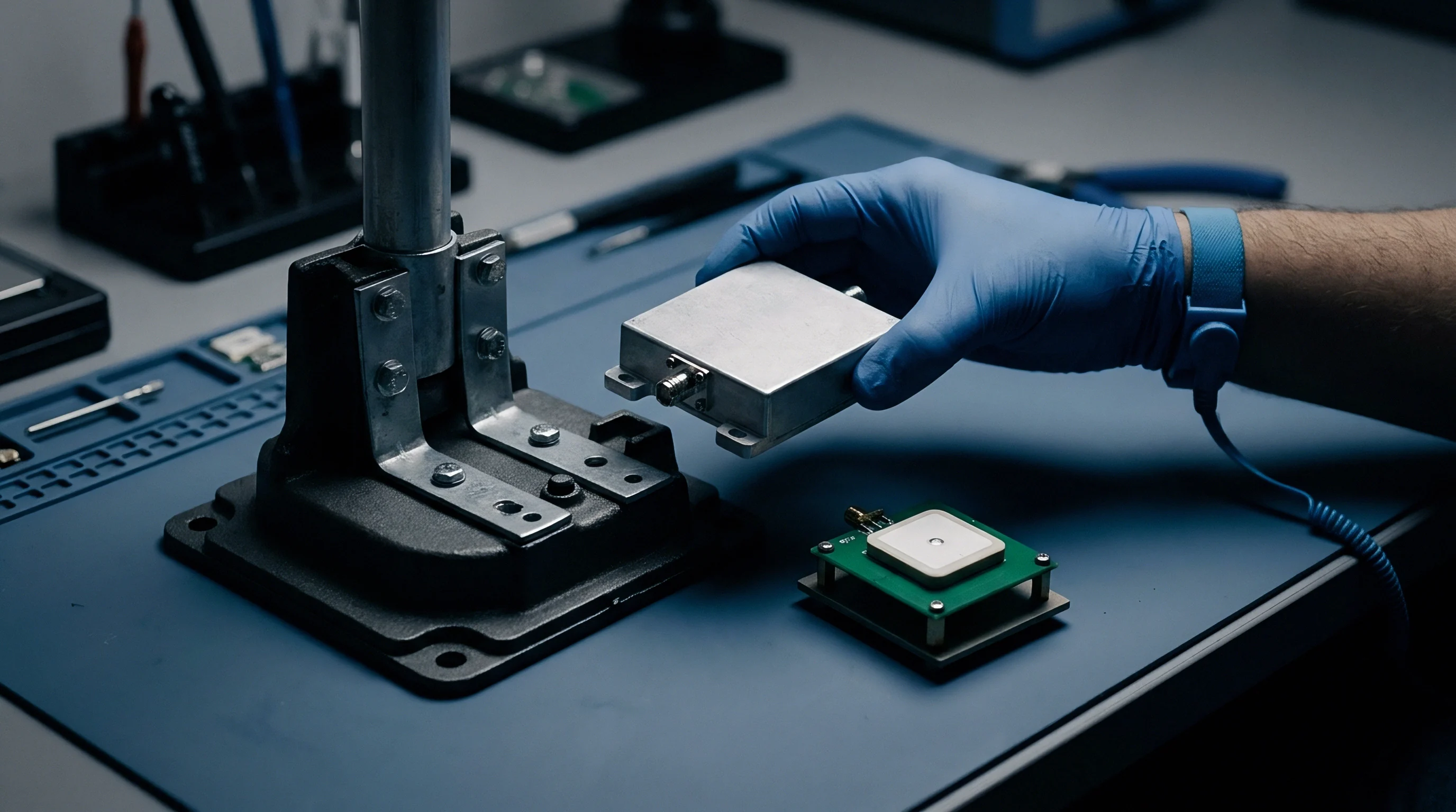

Ledger
Test reports on file with the commission provide the baseline documentation that prevents port seizures. The FCC Office of Engineering and Technology maintains an open database of lab exhibits, circuit descriptions, block schematics, and interior board photographs. Intake audits check these records prior to volume commitment.
To substantiate compliance, a module vendor must supply an active FCC ID comprising a grantee code and product code.

Will Alternate Antennas Trigger Permissive Changes?
Replacing an onboard inverted-F trace with an external dipole changes the field distribution. When layout modifications or alternate radiators alter emissions beyond certified limits, rules define a specific paperwork pathway. A Class I Permissive Change handles small shifts that do not increase reported emissions or degrade RF performance, requiring internal records without an agency submission.
A Class II Permissive Change covers measurable changes in radiated output that remain below statutory limits, requiring fresh lab reports filed through a telecommunications certification body.
An active FCC grantee code establishes legal custody of the equipment authorization while the factory maintains assembly control.
The grantee code identifies the company legally responsible for the certified module. Cross-referencing that code against business registries verifies corporate status and direct responsibility. In grey-market or white-label channels, the FCC file quickly exposes whether a unit represents genuine contract manufacturing or unverified relabeling.
Just as cathodic protection fails when bonding breaks at a hull fitting, regulatory chains break when the entity holding a grant dissolves without transferring authorization.
Purchasing teams audit supplier documentation dossiers against strict intake requirements:
- Form 731 equipment grant certificates confirm the active operational status and emission designators of the radio.
- Accredited test laboratory reports demonstrate radiated spurious measurements across fundamental and harmonic frequencies.
- User manual integration instructions describe required trace layouts, separation distances, and host labeling phrasing under KDB 996369.
- Attestation letters of compliance certify that modular firmware prevents operational frequencies outside authorized national bands.
Contractual commitments must govern regulatory custody. A purchase contract clause stipulating indemnification against grant revocation shifts the economic burden of unauthorized silicon revisions back to the module maker.

Drain
Current peaks during packet bursts determine cell chemistry selection and power trace routing. As a transceiver jumps from microampere sleep modes to a thirty-milliwatt transmit state, the instantaneous surge pulls down the supply rail. Without adequate decoupling capacitance near the pins, the DC rail drops below the operating threshold of the synthesizer, generating phase noise that degrades adjacent channel power ratios.
Section 15.247 allows up to one watt of conducted power into the radiating element for digital modulation systems. Most battery-powered IoT devices run lower, between zero and fourteen dBm, to conserve cell capacity. Producing ten dBm at 2.4 GHz draws thirty to fifty milliamperes from a 3.3-volt rail, while twenty dBm pushes current demand past one hundred and twenty milliamperes.
Conducted output power drops by three decibels when supply voltage ripples exceed fifty millivolts on a thirty-three hundred millivolt rail during packet burst transmission.
| Protocol and Modulation | Carrier Band | Conducted Power | Transmit Current at 3.3V | Sleep Mode Current |
|---|---|---|---|---|
| Bluetooth Low Energy (GFSK) | 2402 to 2480 MHz | 4.0 dBm | 12.5 mA | 1.2 µA |
| IEEE 802.15.4 Zigbee (O-QPSK) | 2405 to 2480 MHz | 8.0 dBm | 28.0 mA | 2.5 µA |
| LoRa Digital Modulation (CSS) | 902 to 928 MHz | 14.0 dBm | 42.0 mA | 1.5 µA |
| Wi-Fi 4 (OFDM, 64-QAM) | 2412 to 2462 MHz | 18.0 dBm | 165.0 mA | 15.0 µA |
A transmitter calibrated at twenty-five degrees Celsius can exhibit a 1.5 dB shift in output power over an industrial range of negative forty to positive eighty-five degrees. This drift reflects baseline semiconductor manufacturing variations where gain compression points move predictably with junction temperature. Batches deviating from that envelope indicate unannounced silicon revisions or unvetted fab transfers.
When an output amplifier saturates heavily to offset an under-voltage rail, harmonic output spikes rapidly past allowed limits.
Periodic advertising packets exhaust reserves through constant oscillator restarts. In duty-cycle governed profiles, total drain tracks the integrated area under transmit bursts, baseband calculation cycles, and sleep windows. Section 15.247 enforces no mandatory duty-cycle ceiling for spread spectrum modulation in the 902 to 928 MHz or 2.4 GHz bands, making battery chemistry the practical constraint on transmission schedules.
Estimating field battery life on remote telemetry nodes remains difficult under fluctuating environmental temperatures and unknown battery self-discharge rates. Engineers routinely calculate ten-year operating life, yet field returns reveal lithium coin cells exhausting capacity inside thirty-six months under unmonitored cold-weather internal impedance spikes. Sourcing engineers protect production budgets by mandating pulsed current discharge characterization on every incoming battery cell lot.
Engineers continue to debate whether aggressive transmitter duty cycling degrades long-term crystal stability under severe thermal swings.

Dock
Port manifests face routine customs reviews for intentional radiator declarations. Federal regulations prohibit importing, marketing, or selling RF equipment without the required equipment authorization on file. Using certified wireless assemblies simplifies clearance because the RF engine holds an existing grant, though the finished host assembly still requires verification as an unintentional radiator.
Final assemblies must display the assigned registration number on the outer housing. Standardized wording on the product label flags the internal radio, using phrases like Contains FCC ID: ABC1234. Where enclosures are too compact for visible permanent labeling, KDB 784748 allows electronic labeling accessible through the system firmware menu.
Sourcing verifies that the vendor delivers certified label artwork and grant exhibits before housing molds are cut.
Host systems undergo Part 15 Subpart B testing to measure noise from digital logic. While the module covers intentional emissions under Subpart C, the surrounding motherboard carries switching supplies, regulators, and high-speed data buses that radiate unintentionally. Integrators pairing a pre-certified radio with host electronics must test under KDB 996369 D04, operating the module in active modes while measuring spurious radiation across the complete product enclosure.
Failure to execute host unintentional verification leads to shipment holds, warehouse quarantines, and administrative fines. Border protection officials inspect commercial invoices, cross-referencing bills of lading with equipment authorization numbers declared in electronic manifest declarations. Sourcing teams maintain synchronized technical dossiers linking the module certificate to the host test summary.
A modular grant shields the radio circuit from certification overhead, yet the final plastic enclosure determines commercial customs compliance.