Meaning
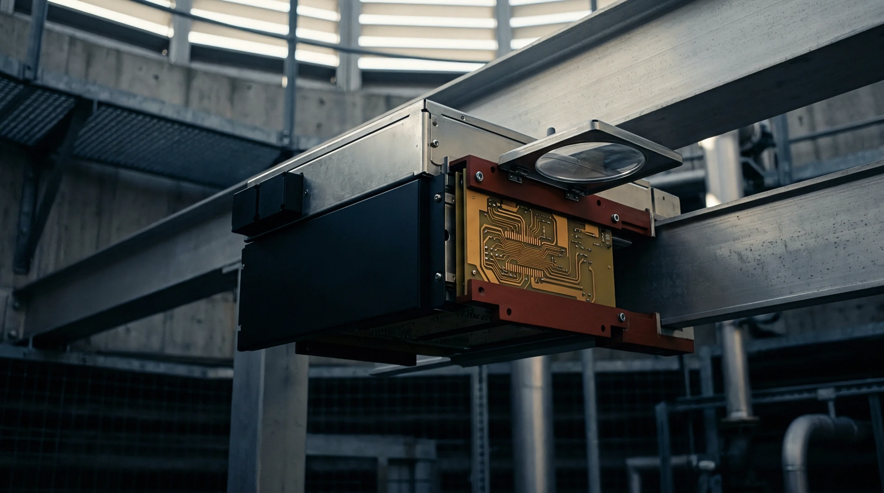
A specialized electronic testing apparatus utilizes an array of spring-loaded pogo pins to make simultaneous contact with test points on a populated printed circuit board. This custom assembly, referred to as an in-circuit test fixture, verifies the correct placement and value of individual resistors, capacitors, and integrated circuits. It operates as the primary quality gate immediately after the reflow soldering process in high-volume production lines.
Mechanical Interface
Aligning hundreds of microscopic test points requires high-precision mechanical guidance and a robust clamping mechanism. The in-circuit test fixture uses a custom-milled top plate and a vacuum or pneumatic press to force the circuit board down onto the spring-loaded pins. This precise downward pressure ensures reliable electrical contact without flexing the board or damaging delicate surface-mount components.
Electrical Diagnostic
Test systems connect to the pins to measure impedance, verify continuity, and check for solder bridges or open circuits. An in-circuit test fixture allows the diagnostic equipment to isolate each component on the board by applying guard voltages to surrounding nodes. This isolation technique ensures that measurements represent the true values of the components under test rather than parallel path impedances.
During a single test run lasting only seconds, the apparatus scans the entire board and identifies defective parts for rework.
Production Integration
Fabricated early in the product introduction phase, the test apparatus must match the physical layout of each board revision. An in-circuit test fixture requires extensive validation to confirm that probe wear or contact resistance does not generate false failures on the line. Maintaining this equipment involves scheduled probe replacement and regular cleaning of the contact tips to ensure consistent results over thousands of test cycles.