Meaning
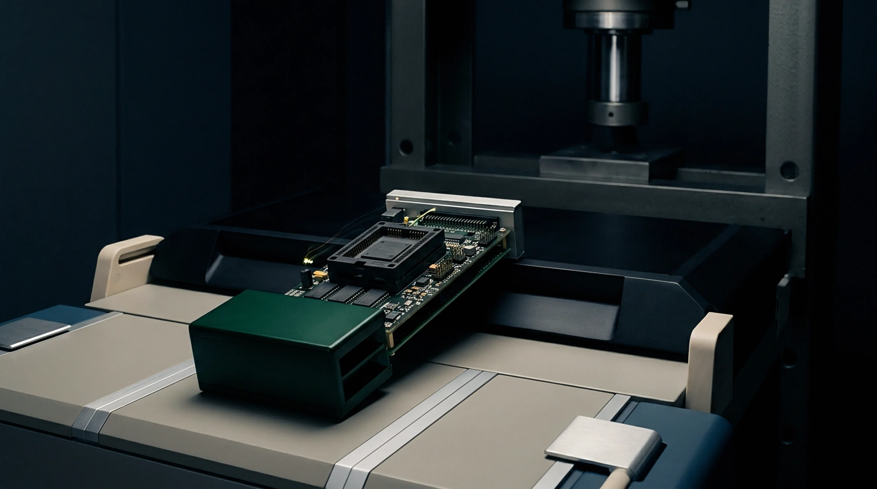
A mechanical housing designed to facilitate temporary high-frequency electrical contact between a radio frequency integrated circuit and a test system during production burn-in or characterization. These millimeter wave test sockets provide the necessary impedance matching and signal integrity required to evaluate devices operating in the 30 gigahertz to 300 gigahertz range. Electromagnetic signals at these frequencies experience significant degradation through standard pin contacts, so the assembly incorporates specialized conductive elastomers or spring probe arrays to minimize insertion loss.
Each unit governs the physical alignment of delicate silicon pads to the test board while maintaining strict thermal control during active switching.
Thermal Geometry
Effective heat dissipation relies on the copper pathways and ceramic headers located inside the housing of the millimeter wave test socket. Engineers select materials based on a coefficient of thermal expansion that matches the device under test to prevent mechanical stress during temperature cycles. Copper alloys provide the conductivity for power delivery, while polyimide insulators maintain the electrical isolation needed for low-noise measurements.
Constant contact pressure ensures the interface remains stable across varying operational states, provided the mounting hardware allows for minute adjustments.
Frequency Integrity
Maintaining signal throughput in a millimeter wave test socket depends on minimizing the electrical path length between the chip and the transmission lines on the printed circuit board. Parasitic inductance and capacitance distort high-speed waveforms, creating reflections that cloud the verification of signal power and phase accuracy. Proper impedance matching requires that the geometry of the contact pins stays consistent with the transmission line environment, ensuring that the total return loss stays within acceptable bounds for the target application.
Shortening the conductive path reduces the risk of resonance at the operating frequency of the device.
Production Certification
Final verification of the hardware occurs during the qualification stage of the manufacturing process when the millimeter wave test socket undergoes validation against a known-good gold standard device. Quality teams compare measured output power levels against the theoretical model to isolate hardware artifacts from silicon failures. Acceptable tolerance levels reflect the cumulative precision of the probe tips and the flatness of the mounting plate.
Rigorous calibration procedures distinguish between equipment noise and real signal loss, ensuring the hardware provides reliable data throughout its entire service life.